Illumination device and method using adaptable source and output format
a technology of illumination device and output format, which is applied in the direction of optics, lighting apparatus, instruments, etc., can solve the problems of maximizing brightness, reducing beam sampling rate, and truncated light is obviously wasted, so as to reduce the beam sampling rate and reduce the cost. , the effect of reducing the beam sampling ra
- Summary
- Abstract
- Description
- Claims
- Application Information
AI Technical Summary
Benefits of technology
Problems solved by technology
Method used
Image
Examples
first embodiment
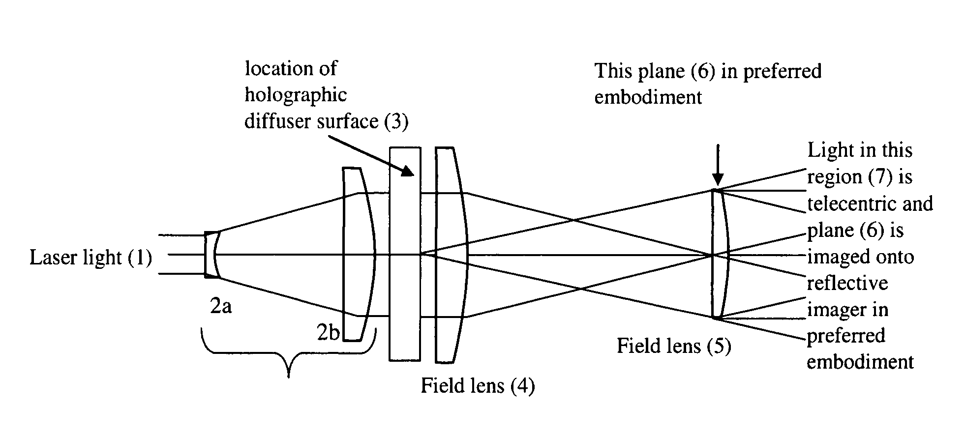
[0090] A beam expander (2) expands the light beam and re-collimates the light. In a first embodiment, the beam expander is comprised of two elements and an intervening beam expansion space. In this embodiment a first plano-cave lens 2a is used to create a conical beam divergence symmetrically centered along the optical axis. A second plano-convex lens 2b is used to halt the beam expansion and re-collimate the laser beam into a second larger diameter beam having its divergence minimized so that its rays are substantially parallel to the optical axis. This larger diameter beam is then directed onto a holographic diffuser (3).
[0091] A holographic diffuser (3) follows the beam expander. In the preferred embodiment this diffuser has the properties of converting an incident laser beam to a plurality of rectangular light cone profiles as shown in FIG. 8C according to the hologram prescription. That is, the light exiting each differential point on the diffuser forms a rectangular cone of li...
second embodiment
[0152] Referring to FIG. 14C, the present system is shown. In this embodiment, the laser light sources are arranged so that the second and third beams (from sources 511b and 511c) are combined from opposite sides of the optical axis. Functionally, this arrangement does not differ from the embodiment of FIG. 14B. This configuration may, however, provide for a more compact package if the laser sources are large enough that they cannot be conveniently located next to each other.
third embodiment
[0153] Referring to FIG. 14D, the present system is shown. In this embodiment, the laser light sources are arranged so that the three beams are combined by a dichroic “X” cube, an optical element known to the projection and optics industry. Functionally, this does not differ from the embodiment of FIG. 14B. This configuration provides for a more compact design of the combiner as the beam splitters occupy the half the space when they are crossed.
[0154] Referring to FIG. 14E, a diagram illustrating the diffraction of light at a single point on a holographic diffuser is shown. As the collimated light passes through the holographic diffuser, it is diffracted so that it exits in a certain cone of light. (“Cone” is used here to refer to an angular area into which the light is radiated.) The cone may be irregularly shaped, as indicated by the dashed line at the right side of the figure. This dashed line is the outline of the diffraction pattern image. The diffraction pattern image is chara...
PUM
 Abstract
Description
Claims
Application Information
 - R&D
- Intellectual Property
- Life Sciences
- Materials
- Tech Scout
- Unparalleled Data Quality
- Higher Quality Content
- 60% Fewer Hallucinations
Browse by: Latest US Patents, China's latest patents, Technical Efficacy Thesaurus, Application Domain, Technology Topic, Popular Technical Reports.
© 2025 PatSnap. All rights reserved.Legal|Privacy policy|Modern Slavery Act Transparency Statement|Sitemap|About US| Contact US: help@patsnap.com


