Ultrasonic method for the accurate measurement of crack height in dissimilar metal welds using phased array

a technology of phase array and ultrasonic inspection, which is applied in the direction of heat measurement, specific gravity measurement, instruments, etc., can solve the problems of not meeting the flaw through-wall sizing requirements of manual ultrasonic examination methods, dissimilar metal welds are long identified as difficult components to inspect, and the welds are highly susceptible to crack initiation, etc., to achieve the effect of facilitating contouring and facilitating transmission and reception of sound energy

Inactive Publication Date: 2007-01-04
BUTSTREETCAR JONATHAN
View PDF0 Cites 80 Cited by
  • Summary
  • Abstract
  • Description
  • Claims
  • Application Information

AI Technical Summary

Benefits of technology

[0015] The transducer assembly shown in FIG. 5, is designed so that the distance separating the transmitter and receiver transducers can be adjusted and then secured. The separation distance is adjusted depending upon the thickness of the material to be tested., the transducer wedge angle and weld geometry

Problems solved by technology

Differences in material properties such as thermal expansion coefficients, Young's modulus, metallurgical grain size and orientation, hardness, resistance to fatigue failure, etc., make these welds highly susceptible to crack initiation caused by high residual stresses, intergranular stress corrosion cracking, or other mechanisms.
Dissimilar metal welds have long been identified as a difficult component to inspect using conventional ultrasonic techniques (the only applicable method for single surface inspection) due primarily to the anisotropic nature of the weld.
Although some vendors have been able to successfully satisfy the flaw detection criteria of Appendix VIII Supplement 10, no vender to date has passed the flaw through-wall sizing requirements using manual ultrasonic examination methods.
This has become a significant problem for the commercial power utilities as nuclear plants in the United States are commonly 30-40 years old.
There are cases where the crack has propagated completely through the weld resulting in water leakage before being detected by visual inspection or throug

Method used


Image

  • Ultrasonic method for the accurate measurement of crack height in dissimilar metal welds using phased array
  • Ultrasonic method for the accurate measurement of crack height in dissimilar metal welds using phased array
  • Ultrasonic method for the accurate measurement of crack height in dissimilar metal welds using phased array

Examples


Embodiment Construction

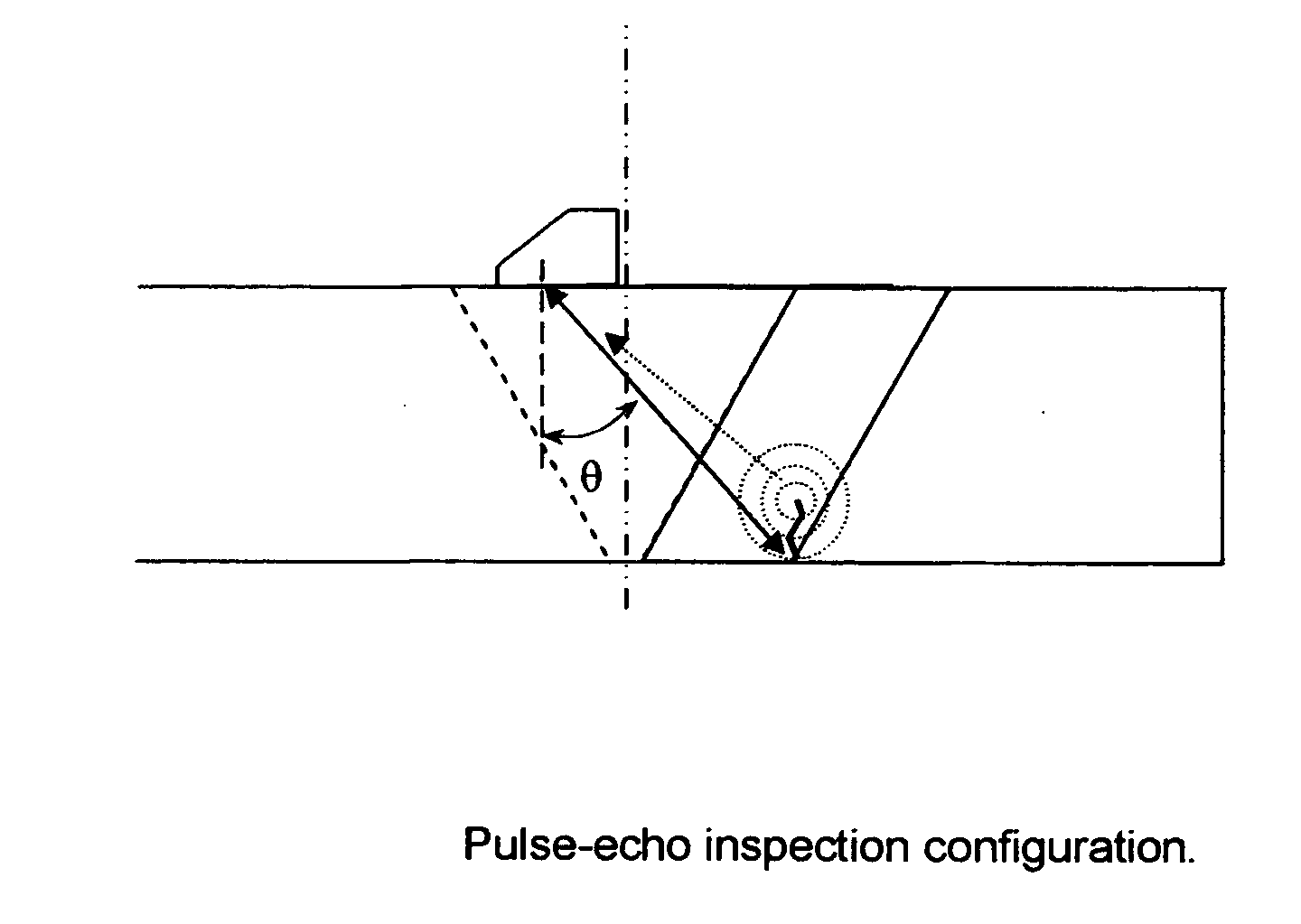
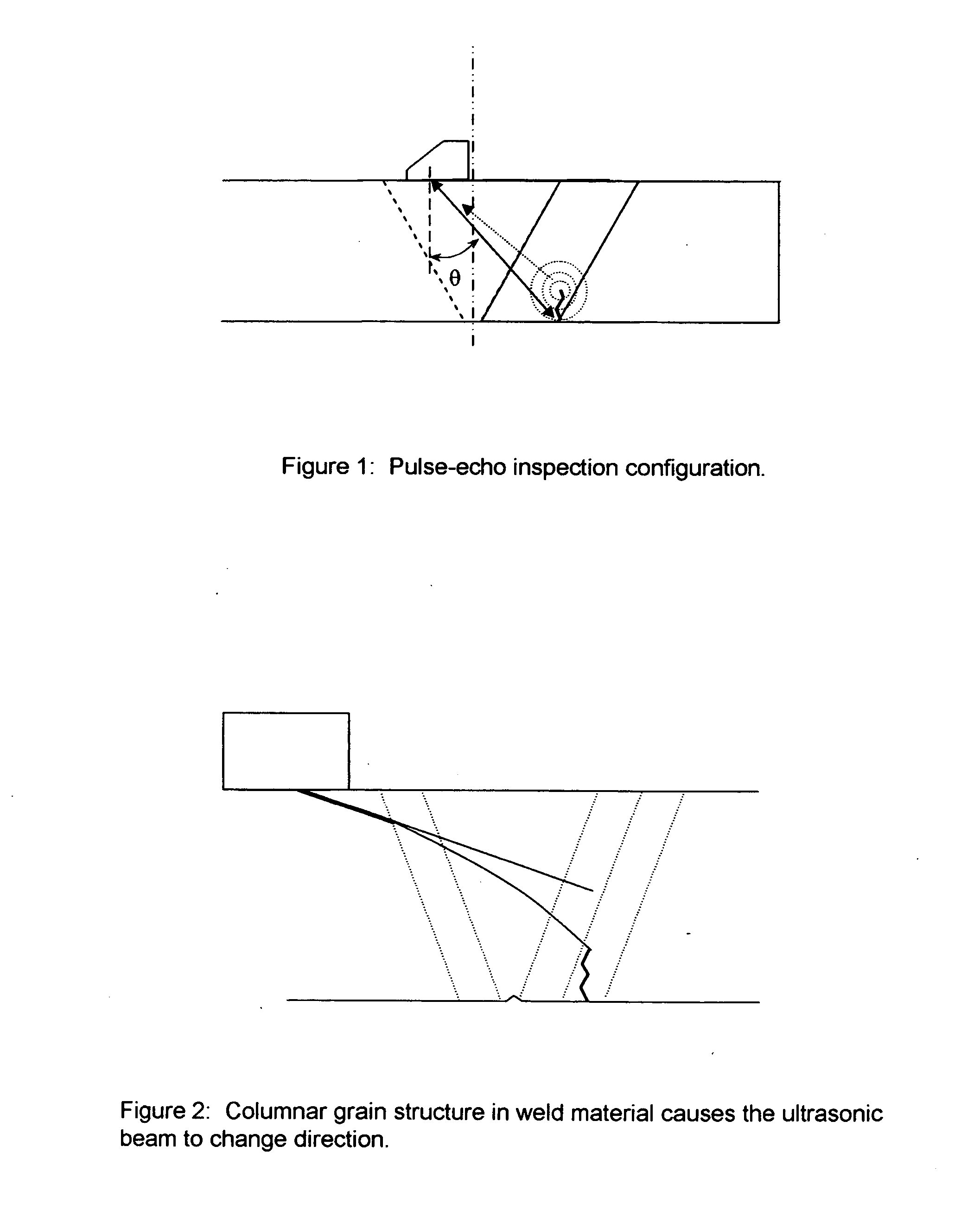
[0030] The present invention is an ultrasonic inspection technique used for the measurement of crack tip depth in large grain materials where crystallographic structure results in beam redirection or bending.

[0031]FIG. 5 is an illustration of the transducer assembly mounted on the OD surface 1 of a circumferntial pipe weld. The transducer assembly consists of two separate ultrasonic transducers 2&3. One transducer acts as a ultrasonic transmitter 3, and the second transducer 2, as the receiver.

[0032] Each transducer housing 2&3, consists of an array of piezoelectric crystals 4, mounted to a wedge 5, where a sound coupling medium is applied between the two components. The array 4, consists of numerous individual piezoelectric crystals (typically between 8-16 crystals). Each crystal is electrically connected to either a transmitter or receiver channel on the ultrasonic phased array system using a shielded cable 6.

[0033] The ultrasonic energy is produced by applying a voltage across...


PUM


Abstract

An ultrasonic method and apparatus utilizing phased array technology for obtaining accurate crack height measurements in materials where crystallographic structure creates beam reduction effects.

Description

1.0 FIELD OF INVENTION [0001] This invention relates overall, to the ultrasonic inspection of dissimilar metal welds where ferritic steel is welded to an austenitic material, and, in particular to the use of phased array ultrasonic hardware in conjunction with a theoretical time-of-flight model in accurately determining the through-wall dimension of a crack. 2.0 BACKGROUND [0002] Dissimilar metal welds are used throughout nuclear power plants wherever a ferritic component is joined to an austenitic component. For example, the reactor vessels of commercial nuclear power facilities are fabricated from thick-sectioned carbon steel materials and claded for corrosion prevention. In contrast, most piping used to carry coolant water and steam to and from the reactor vessel is fabricated from a stainless steel alloy. Where these two components attach, is a weldment that secures two materials that have different material properties. Differences in material properties such as thermal expansio...

Claims


Application Information

Patent Timeline
IPC IPC(8): G01H5/00
CPCG01H5/00G01N29/069G01N29/07G01N29/262G01N29/30G01N2291/267G01N2291/0289G01N2291/0421G01N2291/0422G01N2291/106G01N29/4418
Inventor BUTTRAM, JONATHAN
Owner BUTSTREETCAR JONATHAN
Why Eureka
Try Eureka