Method and Apparatus for Automated, Modular, Biomass Power Generation

a technology of biomass power generation and biomass gasification, applied in the direction of gasifier mechanical details, separation process, filtration separation, etc., can solve the problems of increasing the size of the system footprint, increasing the bulk density of the fuel bed, and reducing the amount of tar. , to achieve the effect of minimizing fouling accumulation, increasing the bulk density of the fuel bed, and maximizing tar reduction

Active Publication Date: 2007-01-11
COMMUNITY POWER CORP
View PDF48 Cites 141 Cited by
  • Summary
  • Abstract
  • Description
  • Claims
  • Application Information

AI Technical Summary

Benefits of technology

[0014] In some aspects, embodiments of the present invention provide methods for converting solid, carbonaceous material to a low tar fuel gas. Methods can include, for example, providing means to control the heating of surfaces (and in some cases all surfaces) downstream of a gasification reactor chamber to a predetermined temperature above the dew point of water, to cease heating the downstream surfaces, and to initiate the gasification process using a heat source to ignite and combust the char stored in the reactor chamber. Methods can also include providing means to control injection of oxidizing gas at several levels along the axial length of the reactor chamber filled with the solid, carbonaceous material, and providing means to control injection of the oxidizing gas to the reactor chamber in a manner to vary in a continuous manner the ratio of the injected oxidizing gas to that from ambient oxidizing air received from any other entrances to the gasification reactor chamber from 0% injected oxidizing gas to 100% ambient air, or from 100% injected oxidizing gas to 0% ambient air. Methods may also include controlling injection of the oxidizing gas to the reactor chamber in a manner to vary the ratio of the oxidizing gas injected at a single axial level from 0% to 100% of the total oxidizing gas required, controlling injection of the oxidizing gas at several levels, and injecting the oxidizing gas in a manner to increase, or decrease, the temperature of the carbonaceous material located downstream of the nozzles. Further, methods may include controlling injection of the oxidizing gas at the plurality of levels, injecting the oxidizing gas in a manner to create a plurality of heated plumes downstream of the injection point and generally parallel to the vertical axis of the chamber, and controlling the movement of the flaming pyrolysis zone in an upstream or downstream direction within the reactor chamber by controlling the fraction of total oxidizing gas injected upstream or downstream of the flaming pyrolysis zone. Methods may also include controlling the movement of the flaming pyrolysis zone in a downstream direction within the reactor chamber by controlling the removal of char and ash from the furthest downstream portion of the fuel bed, and increasing fuel-bed bulk density (as measured in weight per unit volume) by controlling forces applied to the external structure of the gasification reactor of a sufficient magnitude, frequency and duration to cause the materials in the fuel bed to move to occupy a smaller volume following the application of the forces. Methods may further include supplying solid, carbonaceous material into the chamber as needed to replenish an amount of the solid, carbonaceous material that has been reduced in volume by combustion of the carbonaceous materials, collapse of void spaces, controlled increase in fuel-bed bulk density, or removal of char and/or ash from the reactor chamber, and outputting the renewable fuel gas from the reactor chamber.
[0015] In some aspects, the cross sectional area of the gasification chamber, or the length of the gasification chamber, or both, can be selected to maximize tar reduction within a prescribed range of fuel gas flow rates. The low tar fuel gas can be made from a solid carbonaceous fuel generally having a bulk density of greater than 3 pounds per cubic foot. For example, shredded army trash can have a bulk density of 6 pounds per cubic foot. In some cases, the low tar fuel gas can be made from the solid carbonaceous materials such as woody biomass; non-woody biomass; cellulosic products such as cardboard,...

Problems solved by technology

Commonly used techniques for biomass gasification often are hampered by the inability to control the variables of gasification, and thus result in the generation of a fuel gas contaminated with high levels of tars.
These components can add cost, complexity, and increase the size of the system footprint.
Furthermore, the tar-laden water effluent, or large volumes of sand or sawdust contaminated with tars, often need to be cleaned up or treated as a hazardous waste stream in many countries in general, and the USA in particular.
What is more, current approaches for gasification often do not provide effective gas cooling, which can lead to unclean fuel gas.
The cooling of ...

Method used


Image

  • Method and Apparatus for Automated, Modular, Biomass Power Generation
  • Method and Apparatus for Automated, Modular, Biomass Power Generation
  • Method and Apparatus for Automated, Modular, Biomass Power Generation

Examples


example 1

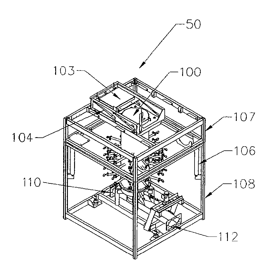
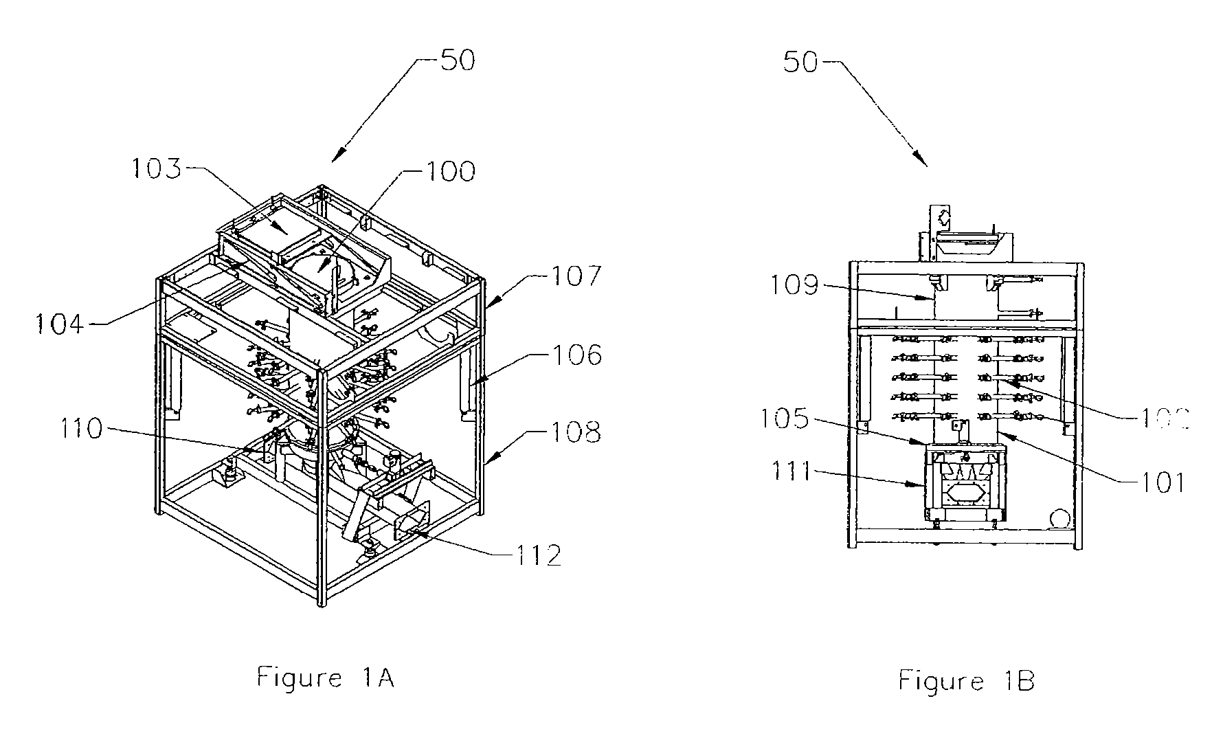
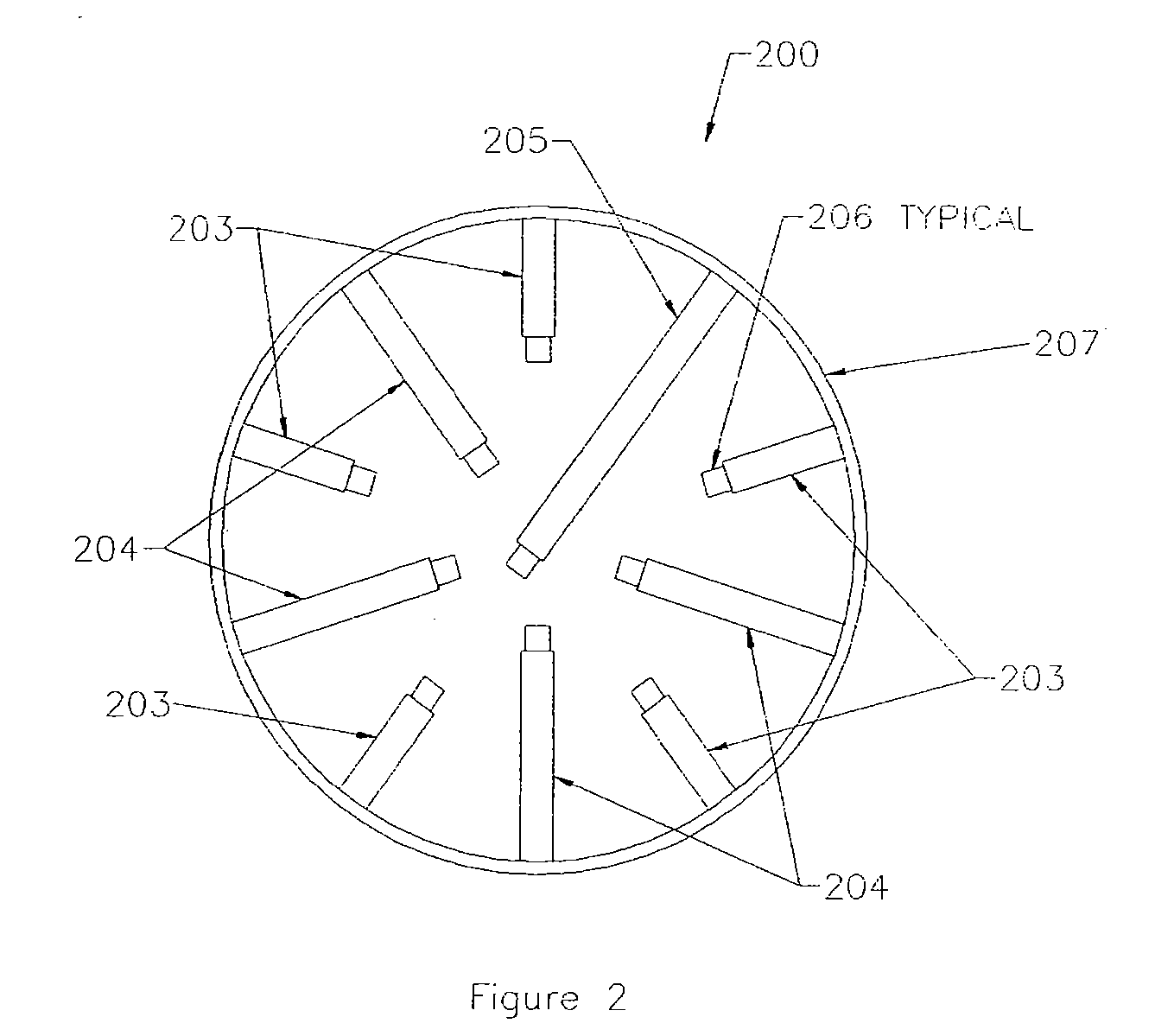
[0093] Softwood chips were used with a nominal size of one inch (2.5 cm) in a gasifier with a 20-inch diameter and 6-inch spacing between five char-air injection levels. During the experiment, the moisture content of the air-dried chips varied between 7% and 8%. The heat exchanger and the filter were preheated for 50 minutes prior to starting to ignite the char bed.

[0094] One of the short char-air injection tubes in the lowest level of the gasifier was removed to provide an open port for ignition. While a mechanical blower was providing suction on the system and flowing air through it, a hand-held propane torch was used to ignite the char at this single char-air tube location. The char-air injection tube was then reinserted. The ignition of the char bed spread quickly upwardly and horizontally across the gasifier. The lower three char-air injection levels reached over 800° C. seven minutes after lighting the char and the woodchip feeder was then started. The flow rate of producer g...

example 2

[0098] Many of the parameters in this test were similar to the test of Example 1, however the engine was operated to produce electricity to satisfy a load of 49.4 kWe using 135 Nm3 / h of producer gas at the elevation of 5720 ft above sea level. If the engine had been at sea level, correcting for the atmospheric pressure ratio, a power output of 60.9 kWe would be expected at a correspondingly higher producer-gas flow rate.

[0099] The gasifier was ignited by removing all five of the short fingers from the lowest char-air injection level. While the producer gas blower was drawing air through the system, a hand-held propane torch was used to ignite the char bed through the five open ports that house the short char-air injection tubes. The moisture content of the wood used in this run was measured and found to vary between 9% and 14%. The dry gas composition in this run was typically 20% CO, 10% CO2, 3% methane, and 18% hydrogen, with the balance nitrogen.

example 3

[0100] Many of the parameters in this test were similar to the test of Example 2, however only two of the short char-air injection tubes were removed for ignition with the hand-held propane torch. Ignition appeared to spread about as quickly up through the char bed, almost as if the gasifier had been ignited at five locations, instead of just two. The moisture content of the feed varied between 7 and 12% in this run. During the steady-state portion of this run, while producing 135 Nm3 / h of producer gas over a period of 146 minutes, 99.6 kg of dry wood chips were fed. This was a feeding rate of 40.9 kg wet wood chips / h. Based on the 49.4 kWe produced by the engine / genset in Example 2, the system requires 0.75 kg dry wood per kWeh.


PUM

PropertyMeasurementUnit
Densityaaaaaaaaaa
Temperatureaaaaaaaaaa
Flow rateaaaaaaaaaa

Abstract

Method and apparatus for generating a low tar, renewable fuel gas from biomass and using it in other energy conversion devices, many of which were designed for use with gaseous and liquid fossil fuels. An automated, downdraft gasifier incorporates extensive air injection into the char bed to maintain the conditions that promote the destruction of residual tars. The resulting fuel gas and entrained char and ash are cooled in a special heat exchanger, and then continuously cleaned in a filter prior to usage in standalone as well as networked power systems.

Description

CROSS-REFERENCES TO RELATED APPLICATIONS [0001] This application claims the benefit of U.S. Provisional Application No. 60 / 694,156, filed Jun. 28, 2005. This application is also related to U.S. Patent Application No. ______, filed Jun. 28, 2006 (Attorney Docket No. 026353-000200US). The entire contents of each of these applications are incorporated herein by reference.STATEMENT AS TO RIGHTS TO INVENTIONS MADE UNDER FEDERALLY SPONSORED RESEARCH OR DEVELOPMENT [0002] The U.S. Government has a paid-up license in this invention and the right in limited circumstances to require the patent owner to license others on reasonable terms as provided for by the terms of SBIR Contract No. DE-FG02-03ER83630 and SMB Contract No. ZDH-9-29047-01, both awarded by the U.S. Department of Energy.BACKGROUND OF THE INVENTION [0003] Embodiments of the invention relate generally to the field of downdraft biomass gasification. More specifically, embodiments of the invention relate to biomass gasification in ...

Claims


Application Information

Patent Timeline
IPC IPC(8): C10J3/46
CPCB01D29/27B01D46/0072C10J2300/0956B01D46/0095C10J3/20C10J3/26C10J3/30C10J3/40C10J3/66C10J3/723C10J2200/09C10J2300/0903C10J2300/0916C10J2300/092C10J2300/0946B01D29/70C10J2200/152B01D46/74
Inventor DIEBOLD, JAMESLILLEY, ARTHURBROWNE, KINGSBURYWALT, ROBBDUNCAN, DUSTINWALKER, MICHAELSTEELE, JOHNFIELDS, MICHAELSMITH, TREVOR
Owner COMMUNITY POWER CORP
Why Eureka
Try Eureka