Spin-coating apparatus and coated substrates prepared using the same

a coating apparatus and coating technology, applied in coatings, thin material processing, semiconductor devices, etc., can solve the problems of inability to obtain uniform coating, failure to satisfy, and difficulty in formation of uniform coating throughout the entire substrate, so as to reduce the ski-jump effect and effectively perform the spin coating operation

Inactive Publication Date: 2007-01-11
LG CHEM LTD
View PDF4 Cites 9 Cited by
  • Summary
  • Abstract
  • Description
  • Claims
  • Application Information

AI Technical Summary

Benefits of technology

[0017] As a result of a variety of extensive and intensive studies and experiments to solve the problems as described above, the inventors of the present invention have discovered, as will be described hereinafter, that, in a spin coating apparatus including a ring-shaped or polygonal auxiliary member, upon mounting a substrate for coating, when spin coating was performed under the condition at which a spaced distance between the inner upper end of the auxiliary member adjacent to the side of substrate and the periphery of the substrate is in a range of 0.03 to 0.8 mm, and a h

Problems solved by technology

However, where a high-viscosity coating solution is applied to the substrate using a conventional spin coating method, viscoelasticity and surface tension of the coating solution result in a conglomeration portion of the coating solution at end portions of the substrate (see 20a of FIG. 1), which in turn, upon curing in such a state, forms a hill, thereby resulting in a ski-jump.
Such a ski-jump leads to difficulty in formation of uniform coating throughout the entire substrate.
In manufacturing a variety of materials such as optical discs, semiconductor substrates, acoustic matching layers and the like, the high-viscosity coating solution is usually spin-coated on the substrate, and it is impossible to obtain a uniformly coated film, due to such a ski-jump.
However, when a UV-curable resin layer is coated on the optical disc via the conventional spin coating method, a resin layer having a thickness of 100 μm exhibited a ski-jump of more than about 45 μm, which was very thick, thus failing to satisfy the above-mentioned specification.
However, this method requires an additional step to remove the bump in an optical disc production process, which in turn further increases manufacturing facility costs and manufacturing process time, thereby lowering manufacturing efficiency, and suffers from problems such as susceptibility to fragility, cracking and bending of the substrate upon cutting the bump.
However, in this case, there are disadvantages such as difficulty to take the disc out of the disc housing after spin coating, contamination risk of a rear side of the disc due to inflow of the resin between the disc and disc housing and then along the side of the disc, and severe contamination of the optical disc due to accumulation of the coating solution in a jig upon repetitive coatings and difficulty to drain it.
Further, although there is reduction in the size of the ski-jump, as compared to the conventional spin coating

Method used


Image

  • Spin-coating apparatus and coated substrates prepared using the same
  • Spin-coating apparatus and coated substrates prepared using the same
  • Spin-coating apparatus and coated substrates prepared using the same

Examples


example 1

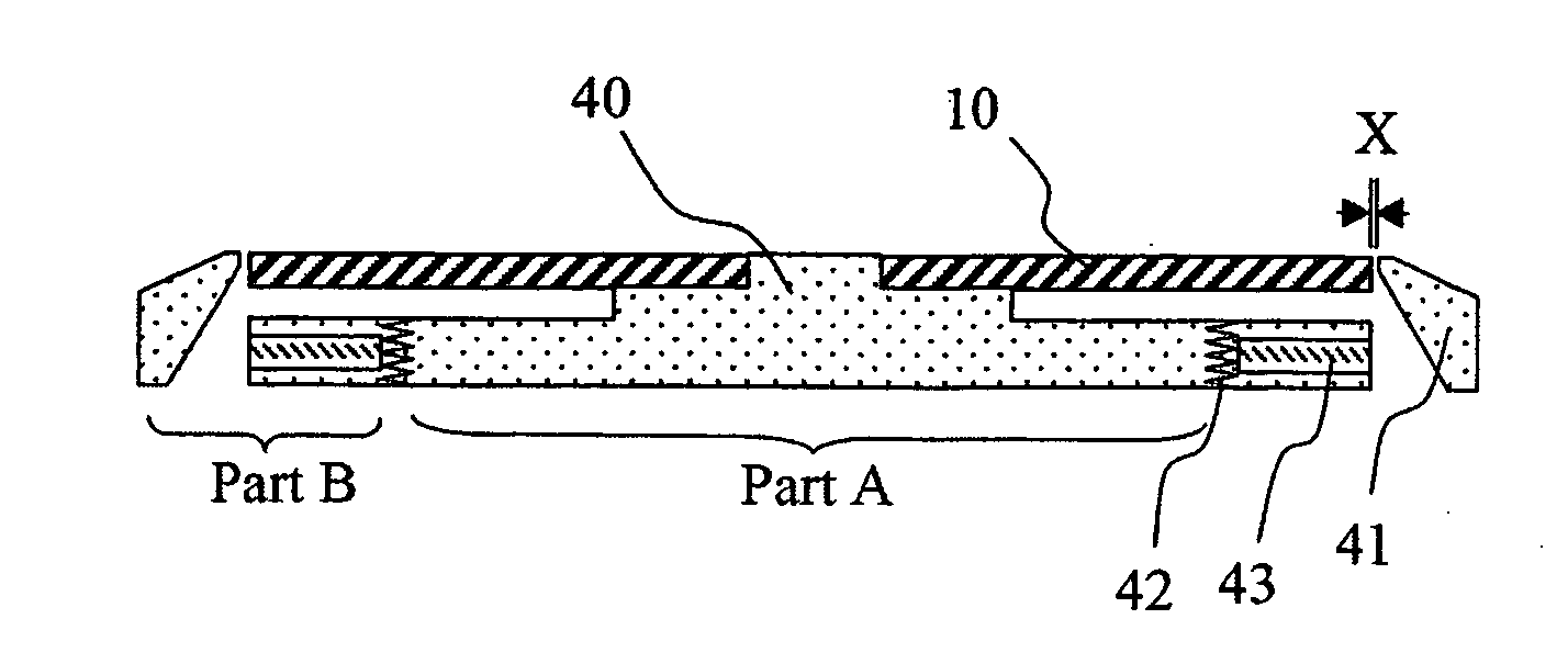
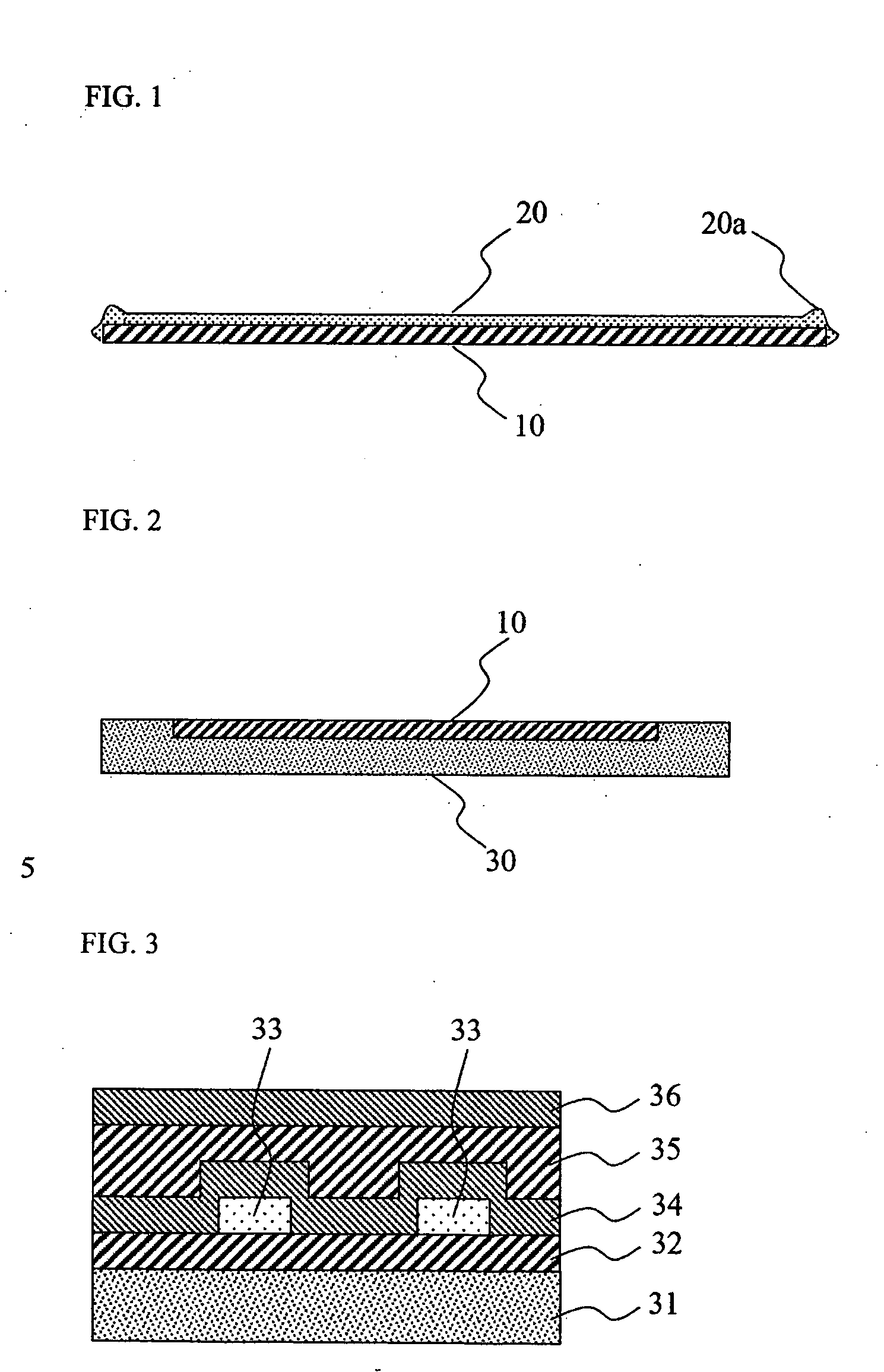
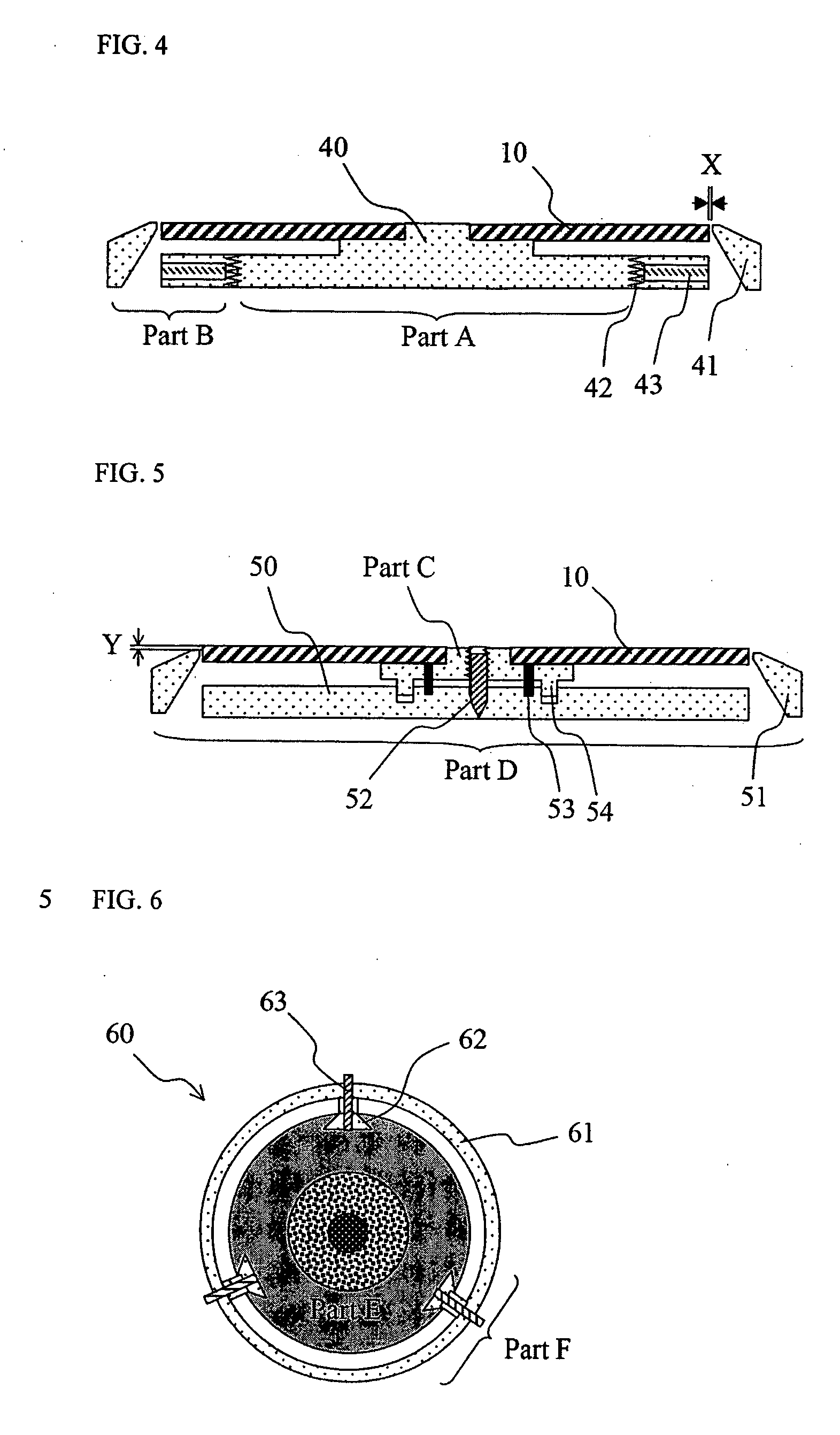
[0050] A turntable, as shown in FIG. 4, was manufactured using an aluminum material. A spaced distance between a peripheral part of a substrate for coating and an inner upper end of a ring-shaped auxiliary member was adjusted to 0.5 mm. Meanwhile, a polycarbonate (PC)-based substrate having a total thickness of 1.1 mm, an outer diameter of 120 mm and an inner diameter (diameter of a central hole) of 15 mm was prepared by injection molding, and a four-layer structure of Ag alloy / ZnS—SiO2 / SbGeTe / ZnS—SiO2 was formed by a sputtering process, thereby preparing a substrate. The resulting substrate was mounted on the turntable and the ring-shaped auxiliary member was rotated to adjust a height of the upper end thereof to be within a deviation range of 0.05 mm, followed by fixing the height via a fixing screw. Next, EB 8402 (made by SK UCB), Irgacure 184 (made by Ciba SC), Irgacure 651 (made by Ciba SC) and a UV-curable resin including methylethylketone were spin-coated using a spin coating...

example 2

[0051] A coated substrate was manufactured in the same manner as in Example 1, except that a turntable was manufactured such that a spaced distance between a periphery of a substrate for coating and an inner upper end of an auxiliary member was 0.1 mm.

example 3

[0052] A coated substrate was manufactured in the same manner as in Example 1, except that a PC-based substrate was prepared to have a thickness of 1.2 mm by injection molding.


PUM


Abstract

Provided is a spin coating apparatus having a ring-shaped or polygonal auxiliary member for use in manufacture of a coated substrate via spin coating, wherein the auxiliary member is positioned adjacent to the side of a substrate for coating, within a range of a spaced distance of 0.03 to 0.8 mm and a range of a height deviation of less than 0.1 mm, upon mounting the substrate. When a surface of a substrate for coating is spin coated with a coating agent using the apparatus of the present invention, it is possible to eliminate or effectively reduce a ski-jump phenomenon at end portions of a coated substrate occurring when spin coating is performed, thereby resulting in uniform coating of a coating solution on the substrate, and it is also possible to effectively decrease contamination of the substrate for coating due to inflow or stay of the remaining coating agent.

Description

FIELD OF THE INVENTION [0001] The present invention relates to a spin coating apparatus. More specifically, the present invention relates to a spin coating apparatus having a ring-shaped or polygonal auxiliary member positioned within an appropriate range of a spaced distance and height deviation from a substrate for coating, so as to eliminate or reduce a “ski-jump (also referred to as a bump, a convex portion, an upheaval, a protrusion, a bead or the like)” phenomenon occurring at end portions of the substrate, upon spin-coating, while effectively performing a spin coating operation, and a coated substrate prepared using the same. BACKGROUND OF THE INVENTION [0002]FIG. 1 schematically illustrates an example in which a coating solution is spin-coated on a substrate for coating, using a conventional method. A conventional spin coating method is performed as follows. A liquid coating solution is dropped on the central portion of the substrate for coating which is rotating at a low sp...

Claims


Application Information

Patent Timeline
IPC IPC(8): B05C13/02H01L29/12
CPCB05C11/08Y10T428/21Y10T428/12528H01L21/6715
Inventor KANG, TAE-SIKLEE, SEONGKEUNHONG, YOUNGJUN
Owner LG CHEM LTD
Why Eureka
Try Eureka