Over-current protection device

Inactive Publication Date: 2007-02-01
POLYTRONICS TECH
View PDF2 Cites 7 Cited by
  • Summary
  • Abstract
  • Description
  • Claims
  • Application Information

AI Technical Summary

Benefits of technology

[0008] The objective of the present invention is to provide a high-voltage over-current protection device. By adding a conductive powder (conductive filler) with a c

Problems solved by technology

If the metal particles are used as the conductive filler, their larger particle size results in less uniform dispersion, and they are prone to be oxidized to cause high resistance.
Since it lacks a rough surface like carbon black, the ceramic powder exhibits poor adhesion with the polyolefin polymer, and consequently, the resistance repeatability of the PTC conductive material is not well controlled.
However, the total resistance of the PTC conductive material after the coupling

Method used


Image

  • Over-current protection device
  • Over-current protection device
  • Over-current protection device

Examples


Embodiment Construction

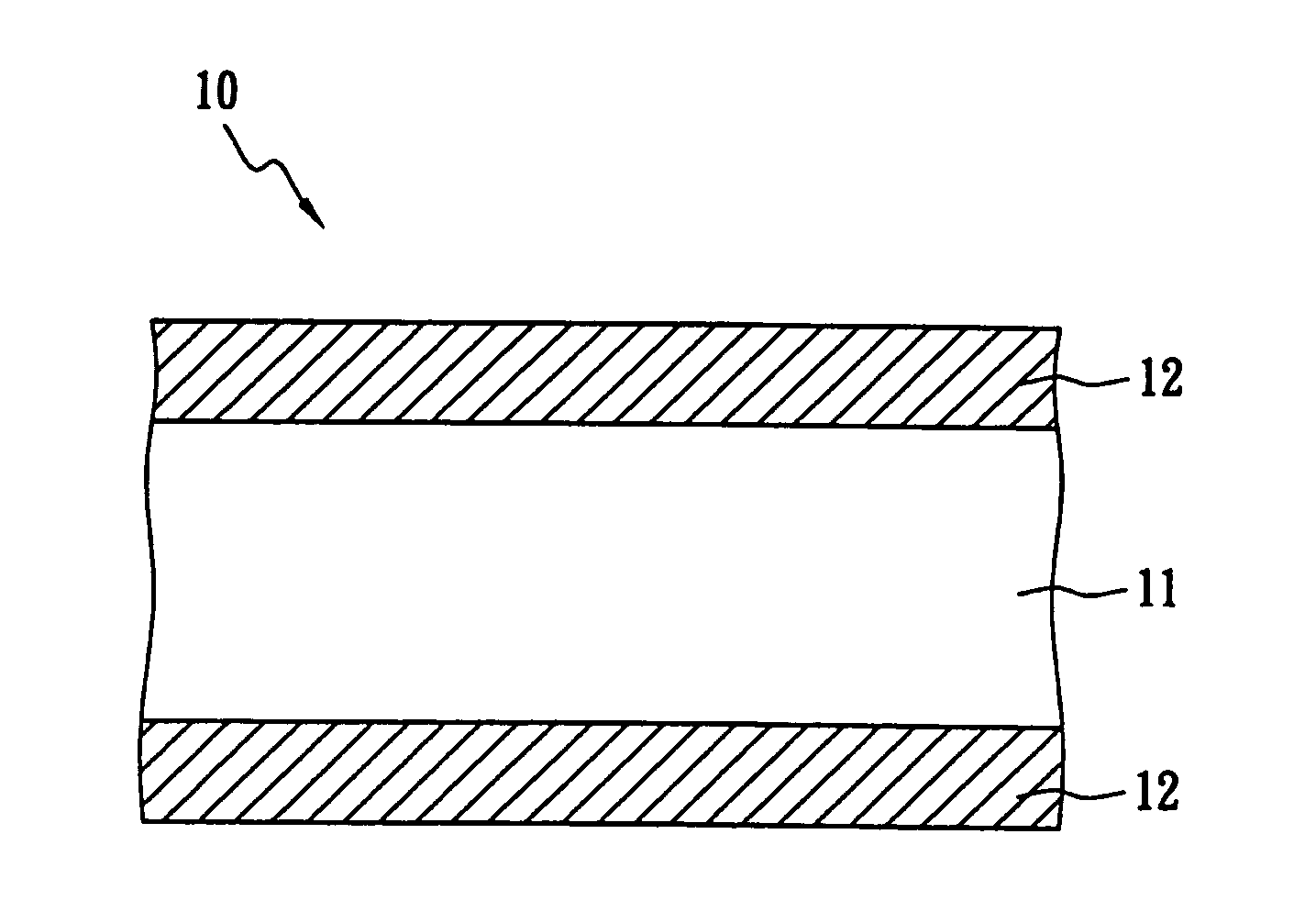
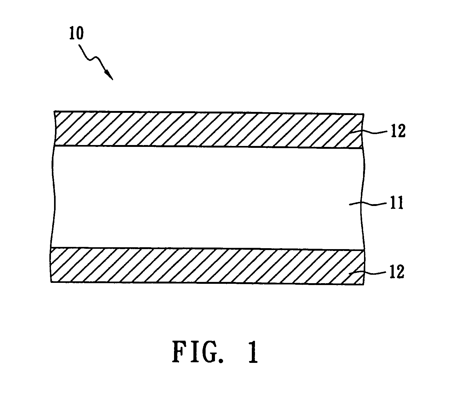
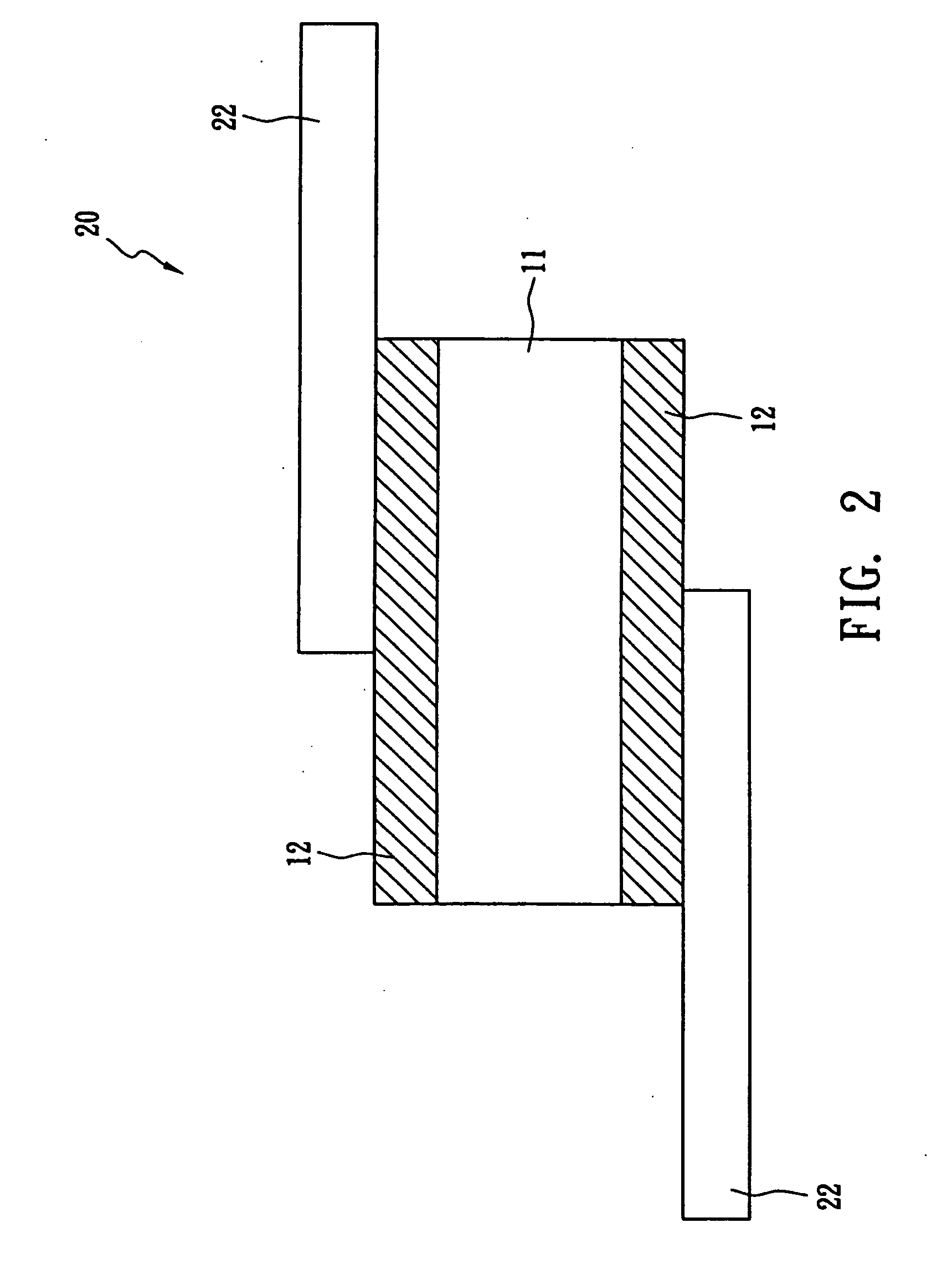
[0018] The following will describe the composition and the manufacturing process of a preferred embodiment of the over-current protection device of the present invention with accompanying figures.

[0019] The composition of the PTC material layer used in the over-current protection device includes a first crystalline polymer (HDPE: density: 0.962 g / cm3; weight: 12.11 g), a second crystalline polymer (HDPE: density: 0.943 g / cm3; weight: 3.03 g), a non-conductive filler (magnesium hydroxide: weight: 4.2 g) and a non-oxide electrically conductive ceramic powder (titanium carbide: weight: 85.75 g). In this embodiment, the first and second crystalline are both high-density polyethylene and the titanium carbide exhibits particle size distribution between 0.1 μm and 10 μm.

[0020] The manufacturing process of the over-current protection device is described as follows. The raw material is fed into a blender (Hakke 600) at 160° C. for 2 minutes. The procedure of feeding the raw material is: ad...


PUM


Abstract

The present invention discloses an over-current protection device comprising two metal foils and a positive temperature coefficient (PTC) material layer. The PTC material layer is sandwiched between the two metal foils and contains at least one crystalline polymer, a non-oxide electrically conductive ceramic powder and a non-conductive filler. The non-oxide electrically conductive ceramic powder exhibits a certain particle size distribution. The PTC material layer presents resistivity below 0.1 Ω-cm.

Description

BACKGROUND OF THE INVENTION [0001] 1. Field of the Invention [0002] The present invention relates to an over-current protection device and, more particularly, to an over-current protection device comprising a positive temperature coefficient (PTC) conductive material. The over-current protection device presents better resistivity and resistance repeatability, especially suitable to the protection of the power source used in portable communication applications. [0003] 2. Description of the Prior Art [0004] The resistance of PTC conductive material is sensitive to temperature change. With this property, the PTC conductive material can be used as current-sensing material and has been widely used in over-current protection devices and circuits. The resistance of the PTC conductive material remains at a low value at room temperature so that the over-current protection device or circuits can operate normally. However, if an over-current or an over-temperature situation occurs, the resista...

Claims


Application Information

Patent Timeline
IPC IPC(8): H01C7/13H01C7/10
CPCH01C7/027
Inventor WANG, SHAU CHEWCHU, FU HUALO, KUO CHANG
Owner POLYTRONICS TECH
Why Eureka
Try Eureka