
Seam-welded air hardenable steel constructions

a technology of air hardening and seam welding, which is applied in the direction of soldering equipment, furnaces, heat treatment equipment, etc., can solve problems such as tendency to crack, and achieve the effects of increasing the area moment of inertia, increasing stiffness, and high quality

Active Publication Date: 2007-02-15
CODD DANIEL SHAWN +1
View PDF18 Cites 1 Cited by
  • Summary
  • Abstract
  • Description
  • Claims
  • Application Information

AI Technical Summary

Benefits of technology

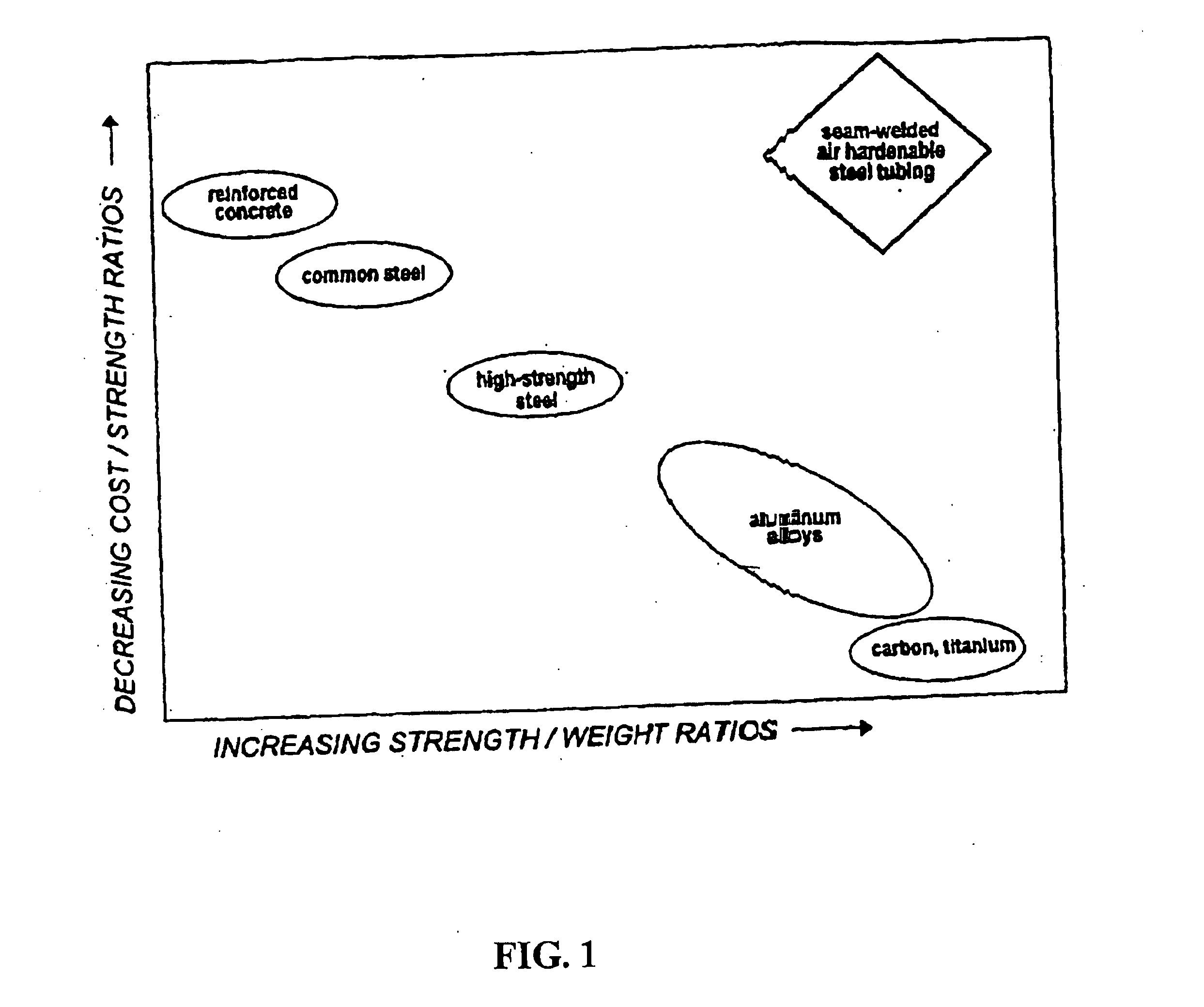
[0028] The preferred embodiment of the present invention is a seam-welded tube of air hardenable martensitic stainless steel. This embodiment provides revolutionary steel tubing that will enable new technologies and find widespread use in many diverse applications including moving vehicles, aircraft, bridges, buildings, fluid and gas transfer piping, elevated railways and roadbeds, heat exchangers, and ships. The principal advantages of this new tubing lie in its high specific strength low cost of production, corrosion resistance, and modular construction and pre-fabrication possibilities. A structural material with these advantages can solve many critical problems currently facing industry, government, and society at large, including pollution, traffic congestion, moving vehicle safety, aging transportation infrastructures, and structural damage, loss of human life and economic waste from seismic and weather related catastrophes.
[0037] Also, it is anticipated that new air hardenable steels containing constituents other than carbon, chrome and iron may be developed in order to improve various characteristics of the steels for various specific applications. Insofar as these new steels could not be seam-welded into a tube without the methods of production taught herein, seam-welded tubing of these steels would be considered to fall within the scope of this patent. In addition, various formulations and newly developed high-strength steel alloys, including Dual Phase, Duplex, High-Strength, and Ultra / Advanced High Strength Steels, would benefit from the high-speed seam welding process described herein. Virtually any alloy that has the tendency to form a martensitic microstructure in the HAZ, after high speed welding, can utilize this process to make the weld joint softer, more ductile, and less prone to cracking once cooled.

Problems solved by technology

As defined herein, an air hardenable steel is one that when welded and processed in a prior art tube mill will tend to crack.

Method used


Image

  • Seam-welded air hardenable steel constructions
  • Seam-welded air hardenable steel constructions
  • Seam-welded air hardenable steel constructions

Examples


example 1

Tubing

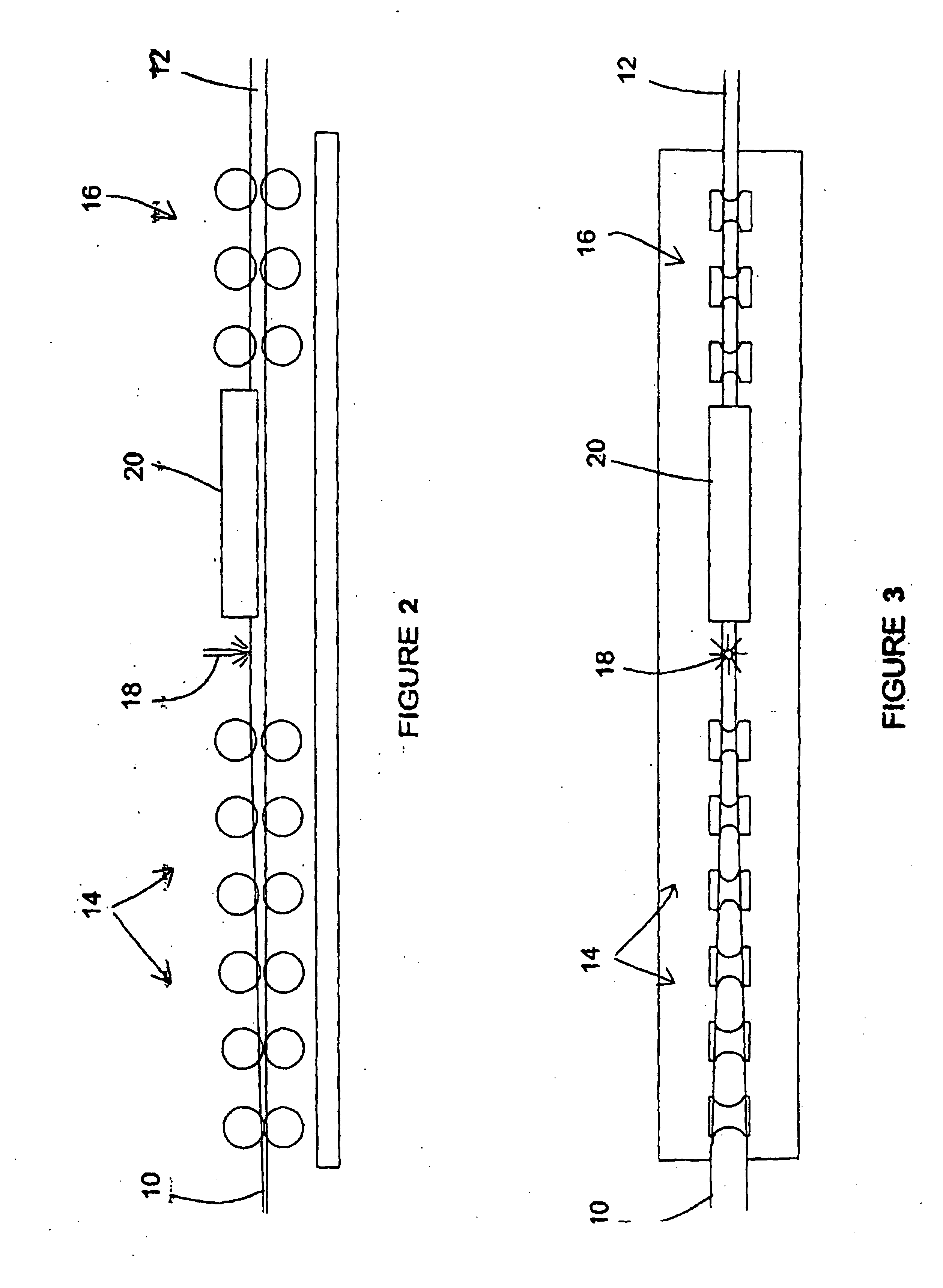
[0101] A 100-foot run of tubing of 1.125″ OD diameter with 0.020″ wall thickness was manufactured. It was manufactured on a mill of the present invention from 3.555″ width type 410 stainless steel strip from Ulbrich Steel of Fresno, Calif., in a manner provided herein above.

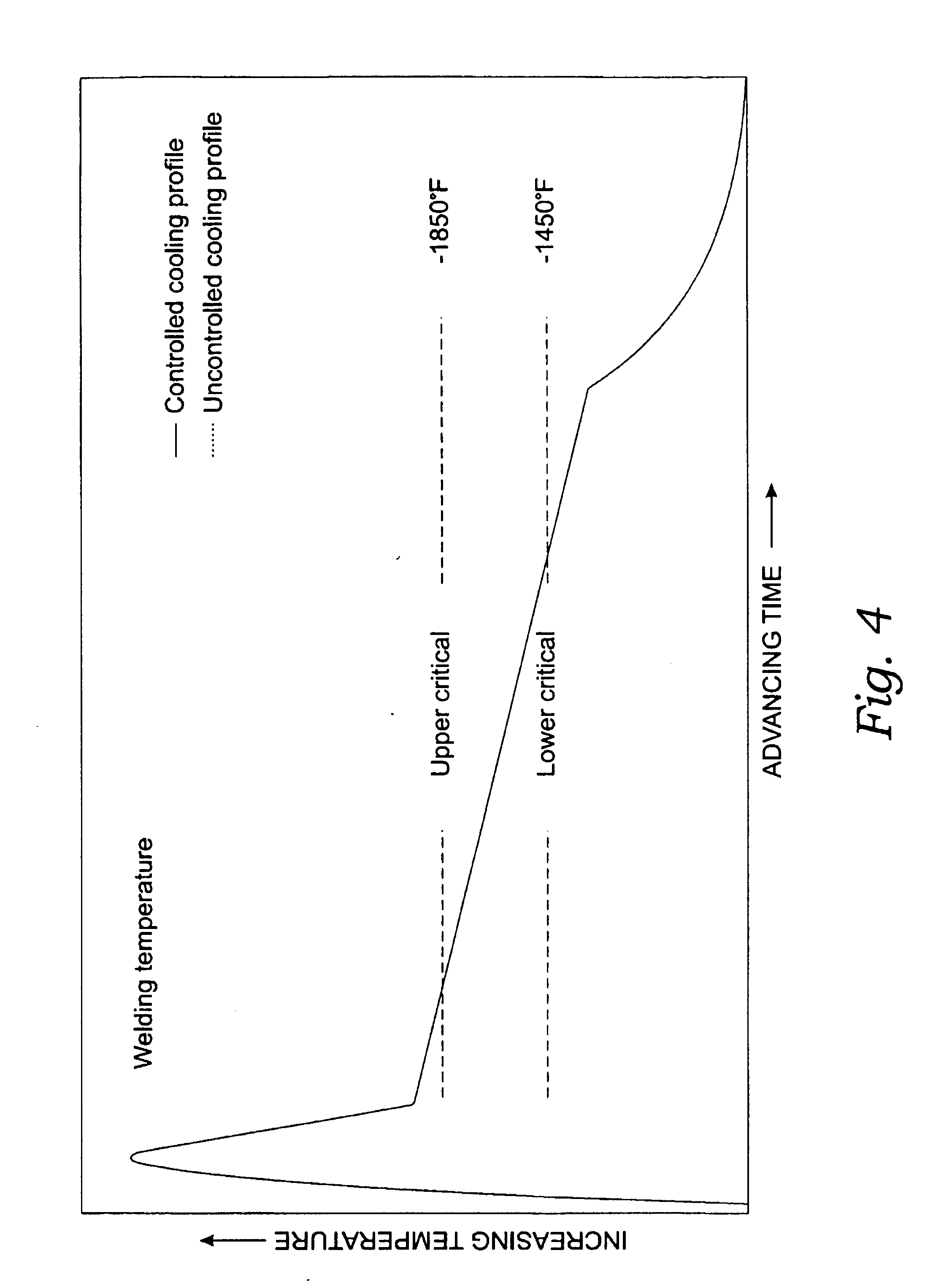
[0102] The welding machine used on the mill was a Lincoln® Squarewave TIG 255, manufactured by the Lincoln Electric Company, of Cleveland, Ohio, and was set at approximately 35 amps in an argon atmosphere. No filler was added. The feed speed of the stainless steel strip into the weld box was two inches per second. The welded tubing was subjected to positively controlled cooling through use of an acetylene torch positioned downstream of the weld box. The flame thereof was adjusted so the heat-affected zone cooled slowly from the upper to the lower critical temperature, the difference between the natural and the controlled cooling rate being represented by FIG. 4. It was estimated that the controlled coolin...

example 2

Bicycle Frame

[0103] Tubing sections from the above run were cut and assembled into a bicycle frame with other drawn tubing. The drawn tubing included in the assembled frame included type 410 stainless steel drawn tubing sections of 0.5″ and 0.625″ OD with 0.020″ wall thickness for the rear triangle. The seam-welded and drawn tubing sections were assembled by hand via butt welding using a Lincoln® Squarewave TIG 255, manufactured by the Lincoln Electric Company, of Cleveland, Ohio using standard type 410 stainless filler rod supplied by San Diego Welding Supply of San Diego, Calif. and modulating the amperage of the welder between approximately 8 to 10 amps. The assembled frame was then heat treated in a batch-type vacuum furnace to a range of 1800 to 1850° F. Certified Metalcraft of El Cajon, Calif. provided the heat-treating furnace. The heat-treating was performed to SAE / AMS 2759 / 5D and MIL-H-6875 specifications.

[0104] The bicycle using this frame was subjected to rigorous field...

example 3

Tension Fatigue at Room Temperature

[0105] Fatigue testing at room temperature was performed to generate data concerning the strength of a hardened, seam-welded stainless steel tube of the present invention that was hardened in a manner similar to that of the bicycle frame.

[0106] It was believed the testing would show none of the cracks typically found in the heat-affected zone of finished tubing of the prior art. The tube tested, after it was hardened, was a piece of the tube run described in Example 1. The test piece was tested in accordance with MIL-STD-1312-11A. The work piece was subjected to 130,000 cycles with a low load of 500 pounds (7,000 psi) and a high load of 5,000 pounds (70,000 psi) of axial tension. This piece was not tested to failure.

[0107] This testing proved that at least one method of the present invention does not produce the tubes of the prior art that had visible and invisible cracks, which would initiate failure in the weld zone.


PUM

PropertyMeasurementUnit
Percent by massaaaaaaaaaa

Abstract

The present invention provides seam-welded, air hardenable steel tubes, methods of manufacturing seam-welded air hardenable steel tubes, tube mills for practicing such methods and applications for using seam-welded, air hardenable steel tubing of the present invention.

Description

RELATED APPLICATIONS [0001] This application is a continuation-in-part of my co-pending U.S. application Ser. No. 10 / 519,910, filed Dec. 30, 2004.BACKGROUND OF THE INVENTION [0002] The present application is related to seam-welded, air hardenable steel structures, tubing and pipe, structures created therefrom and methods for manufacturing seam-welded, air hardenable steel constructions. [0003] A seam-welded, air hardenable steel tube substantially free of cracks in the weld zone has not been proposed in the prior art. “Air hardenable steel” is herein defined as steel that reaches a level of hardness sufficient to cause cracking when processed in a prior art roller-forming tube mill. Other steels which are sometimes called “air hardenable” do not reach a comparable level of hardness and therefore do not crack when processed in a prior art roller-forming tube mill; these steels are categorized herein as “partially or non-air hardenable” steels. [0004] An example of a non-air hardenabl...

Claims


Application Information

Patent Timeline
IPC IPC(8): A47J36/02
CPCB23K9/0253B23K9/167B23K2201/28B23K2201/006B23K2201/06B23K26/265B23K26/262B23K2101/006B23K2101/06B23K2101/28
Inventor MCCRINK, EDWARD J.
Owner CODD DANIEL SHAWN
Learn More