Rare-earth alloy, rare-earth sintered magnet, and methods of manufacturing

a technology sintered magnets, applied in the field of rare earth alloys, can solve the problems of reducing production efficiency, difficult to achieve good magnetic properties, and large grain size and the formation of equiaxed crystals, and achieve uniform treatment and short period of time

Inactive Publication Date: 2007-03-08
SAKAKI KAZUAKI +4
View PDF10 Cites 10 Cited by
  • Summary
  • Abstract
  • Description
  • Claims
  • Application Information

AI Technical Summary

Benefits of technology

[0008] It is therefore an object of the present invention to provide a rare-earth alloy which can be uniformly treated in a short period of time when heat treated as a thin strip-like ingot. It is also an object of the invention to provide a method of manufacturing such alloys.

Problems solved by technology

Yet, in a casting process carried out using a box-shaped mold, the inner portions of the ingot tend to cool more slowly than the cooling rate at which columnar crystals form, resulting in a larger grain size and the formation of equiaxed crystals.
One way to overcome this problem is to reduce the thickness of the ingot, but doing so lowers the production efficiency.
Coarsening of the structure and equiaxed crystal formation leads to segregation within the ingot, which adversely impacts the magnet structure following sintering and solution treatment, making it difficult to achieve good magnetic properties.
However, it has been shown that sintered magnets produced from ingots with a microcrystalline structure as the starting material, while having a better coercivity than sintered magnets made from ingots cast in a box-shaped mold, have an inferior residual flux density and maximum energy product (JP-A 9-111383).

Method used


Image

  • Rare-earth alloy, rare-earth sintered magnet, and methods of manufacturing
  • Rare-earth alloy, rare-earth sintered magnet, and methods of manufacturing
  • Rare-earth alloy, rare-earth sintered magnet, and methods of manufacturing

Examples


example 1

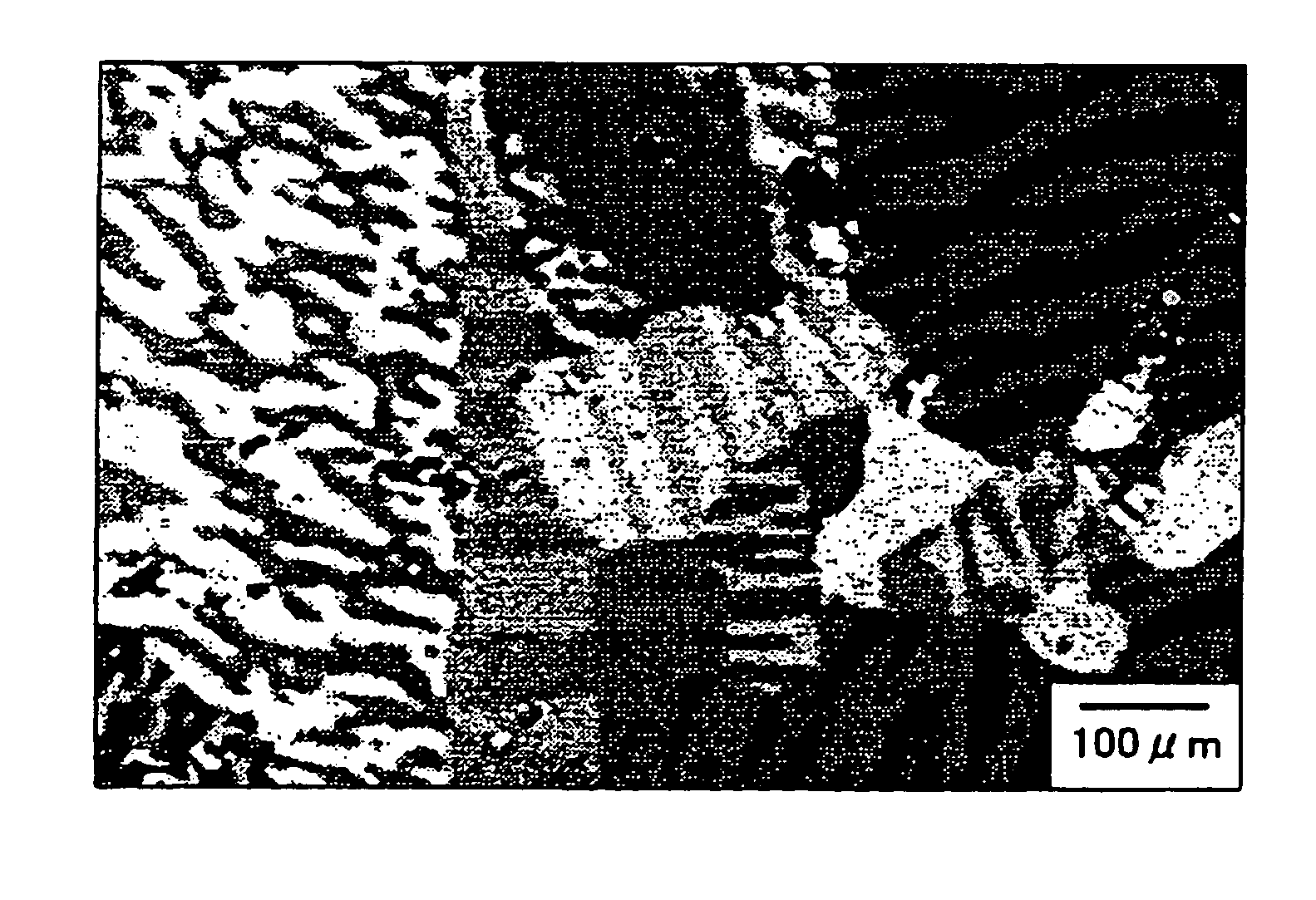
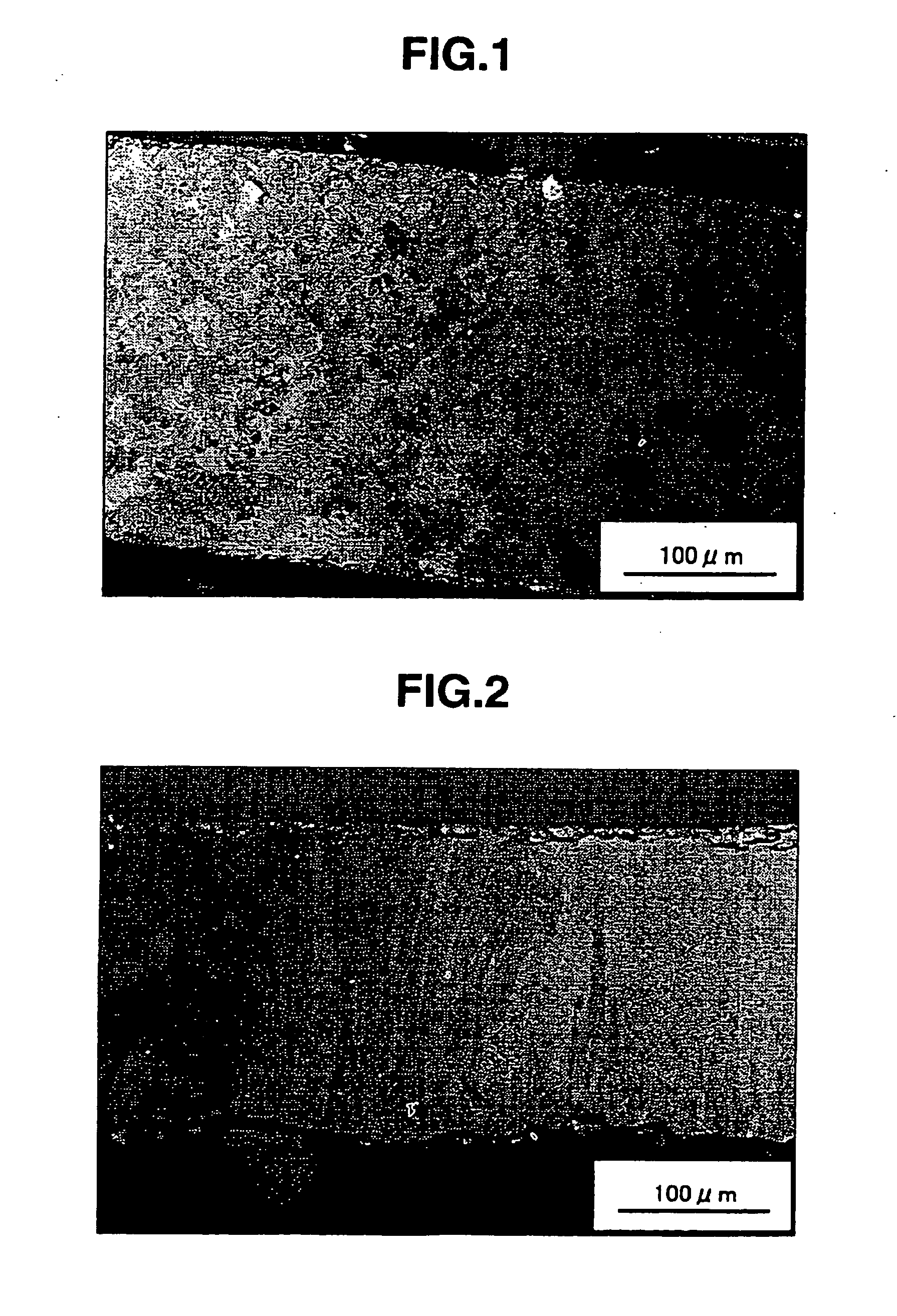
[0069] A Sm2Co17-based magnet ingot was produced by formulating a starting material composed of 25.5 wt % samarium, 16.0 wt % iron, 5.0 wt % copper and 3.0 wt % zirconium, with the balance being cobalt. The composition was placed in an alumina crucible and melted in an induction furnace under an argon gas atmosphere, following which the melt was strip-cast using a single water-cooled roll (circumferential speed of roll, 1 m / s) at a melt temperature of 1350° C. FIG. 1 is a polarizing microscope image of the microstructure in the resulting alloy. The alloy had a plate thickness of 0.3 mm and an average crystal grain size of 10 μm. Equiaxed crystals having a grain size of 1 to 200 μm accounted for 95 vol % of the crystals, with the remainder being columnar crystals. “Average crystal grain size”, as used here and below, refers to the average size of the crystal grains expressed as the diameter of a sphere of the same volume.

[0070] The Sm2Co17-based magnet ingot was then heat-treated in...

example 2

[0076] A Sm2Co17-based magnet ingot was produced by formulating a starting material composed of 20.0 wt % samarium, 5.5 wt % cerium, 14.0 wt % iron, 5.0 wt % copper and 3.0 wt % zirconium, with the balance being cobalt. The composition was placed in an alumina crucible and melted in an induction furnace under an argon gas atmosphere, following which the melt was strip-cast using a single water-cooled roll (circumferential speed of roll, 2.5 m / s) at a melt temperature of 1400° C. The alloy had a plate thickness of 0.2 mm and an average crystal grain size of 30 μm. Equiaxed crystals having a grain size of 1 to 200 μm accounted for 80 vol % of the crystals, with the remainder being columnar crystals.

[0077] The Sm2Co17-based magnet ingot was then heat-treated in a heat treatment furnace under an argon atmosphere at 1100° C. for 2 hours. Following the completion of heat treatment, the ingot was quenched. The size of the crystal grains in the resulting Sm2Co17-based magnet alloy was meas...

examples 3 and 4

[0085] In each example, a Sm2Co17-based magnet ingot was produced by formulating a starting material composed of 25.5 wt % samarium, 14.0 wt % iron, 4.5 wt % copper and 2.8 wt % zirconium, with the balance being cobalt. The composition was placed in an alumina crucible and melted in an induction furnace under an argon gas atmosphere, following which the melt was strip-cast using a single water-cooled roll (circumferential speed of roll, 1 m / s) at a cooling rate of −2000° C. / s. The resulting Sm2Co17-based magnet ingot was heat-treated in a heat treatment furnace under an argon atmosphere at 1200° C. for 2 hours. Following the completion of heat treatment, the ingot was quenched. The structures of the resulting Sm2Co17-based magnet alloys were examined under a polarizing microscope and a scanning electron microscope, in addition to which the average crystal grain sizes were measured.

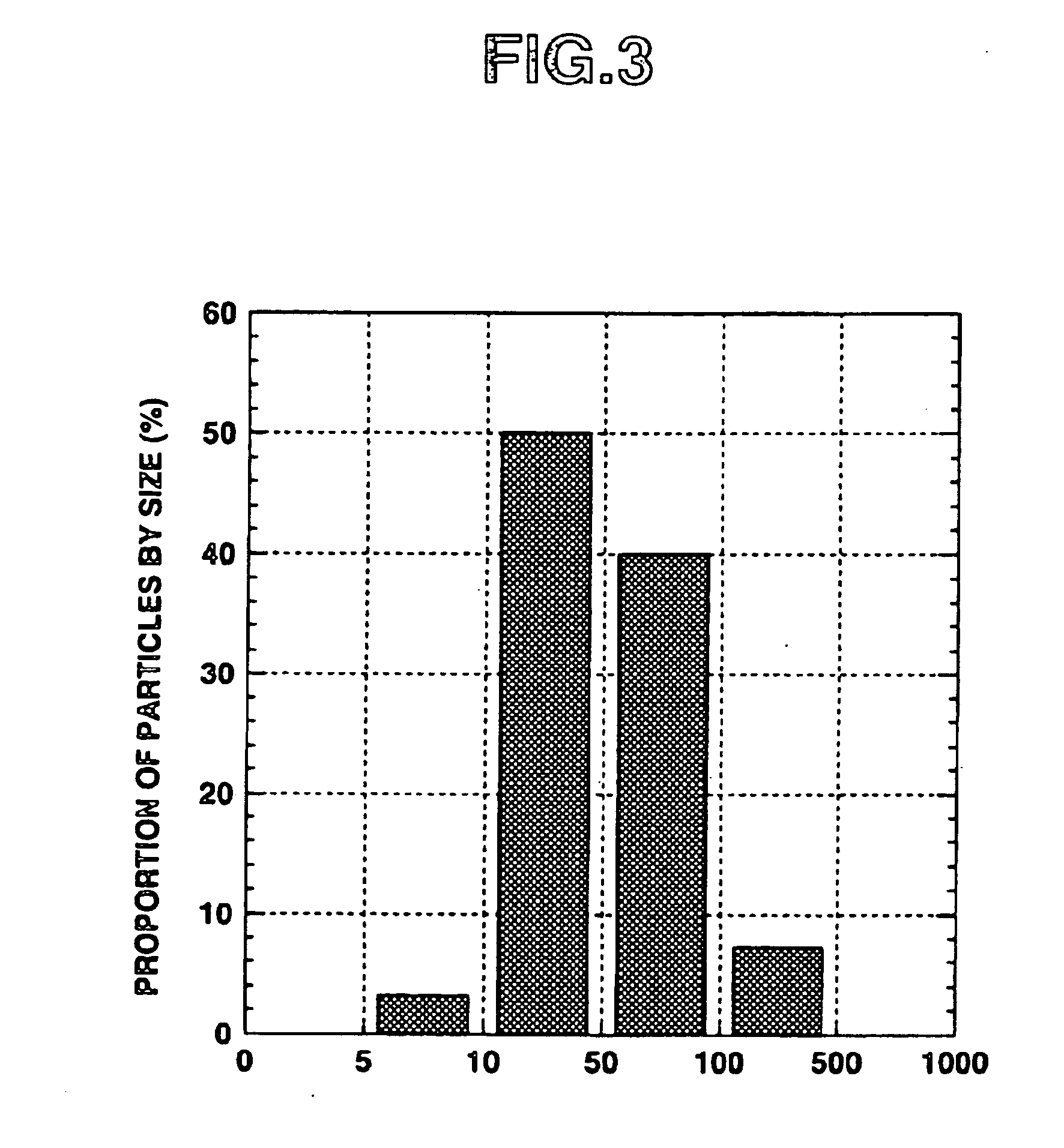
[0086] The Sm2Co17-based magnet alloys were crushed to a size of about 500 μm or less with a jaw crush...


PUM

PropertyMeasurementUnit
crystal grain sizeaaaaaaaaaa
particle sizeaaaaaaaaaa
temperatureaaaaaaaaaa

Abstract

A rare-earth alloy ingot is produced by melting an alloy composed of 20-30 wt % of a rare-earth constituent which is Sm alone or at least 50 wt % Sm in combination with at least one other rare-earth element, 10-45 wt % of Fe, 1-10 wt % of Cu and 0.5-5 wt % of Zr, with the balance being Co, and quenching the molten alloy in a strip casting process. The strip-cast alloy ingot has a content of 1-200 μm size equiaxed crystal grains of at least 20 vol % and a thickness of 0.05-3 mm. Rare-earth sintered magnets made from such alloys exhibit excellent magnetic properties and can be manufactured under a broad optimal temperature range during sintering and solution treatment.

Description

BACKGROUND OF THE INVENTION [0001] 1. Field of the Invention [0002] The present invention relates to rare-earth alloys and a method of manufacturing such alloys. The invention also relates to Sm2Co17-based sintered magnets and a method of manufacturing such magnets. [0003] 2. Prior Art [0004] The sintered magnet materials used in Sm2Co17-based permanent magnets are typically produced by a process which includes milling an alloy ingot of a regulated composition to a particle size of 1 to 10 μm, pressing and shaping the resulting powder in a magnetic field to form a powder compact, sintering the powder compact in an argon atmosphere at 1100 to 1300° C., and typically about 1200° C., for a period of 1 to 5 hours, then solution-treating the sintered compact. Next, the solution-treated compact is generally subjected to aging treatment in which it is held at a temperature of 700 to 900° C., and typically about 800° C., for about 10 hours, then gradually cooled to 400° C. or less at a rate...

Claims


Application Information

Patent Timeline
Patent Type & Authority Applications(United States)
IPC IPC(8): H01F1/055H01F41/02
CPCB22F2003/248B22F2009/041H01F41/0273H01F41/0266H01F41/026H01F1/0557B22F2998/10C22C1/0441C22C19/007C22C19/07B22F9/04B22F3/02B22F3/10B22F3/24
Inventor SAKAKI, KAZUAKISATO, KOJIHASHIMOTO, TAKAHIRONAKAMURA, HAJIMEMINOWA, TAKEHISA
Owner SAKAKI KAZUAKI
Why Eureka
Try Eureka