Ptc thermistor and method for protecting circuit

a thermistor and circuit technology, applied in the direction of positive temperature coefficient thermistors, non-metal conductors, conductors, etc., can solve the problems of reducing conductivity, deterioration of adhesive bonding between the conductive member and the electrode, and difficulty in current flow, so as to achieve the effect of increasing the electrical resistan

Active Publication Date: 2007-03-15
TYCO ELECTRONICS RAYCHEM KK
View PDF7 Cites 20 Cited by
  • Summary
  • Abstract
  • Description
  • Claims
  • Application Information

AI Technical Summary

Benefits of technology

[0010] This invention is a PTC thermistor provided with a conductive member having PTC characteristics and two electrodes each placed in two different locations on the conductive member, characterized by the conductive member and at least one of the two electrodes being bonded via an adhesive which has conductivity and which at the same time deteriorates in an overheated state and irreversibly increases the electrical resistance.

Problems solved by technology

According to the PTC thermistor as described above, when an excessive amount of current flows between the two electrodes, the conductive member first expands thermally by self-generating heat through Joule heat, so that it becomes difficult for current to flow.
The conductive member continues to self-generate heat even when it becomes difficult for current to flow, so that when heat generation continues for a long time, the adhesive bonding the conductive member and the electrodes deteriorates and conductivity is decreased (as a result of the electrical resistance increasing).

Method used


Image

  • Ptc thermistor and method for protecting circuit
  • Ptc thermistor and method for protecting circuit
  • Ptc thermistor and method for protecting circuit

Examples


first embodiment

[0020] this invention, shown in FIGS. 1 and 2, is explained.

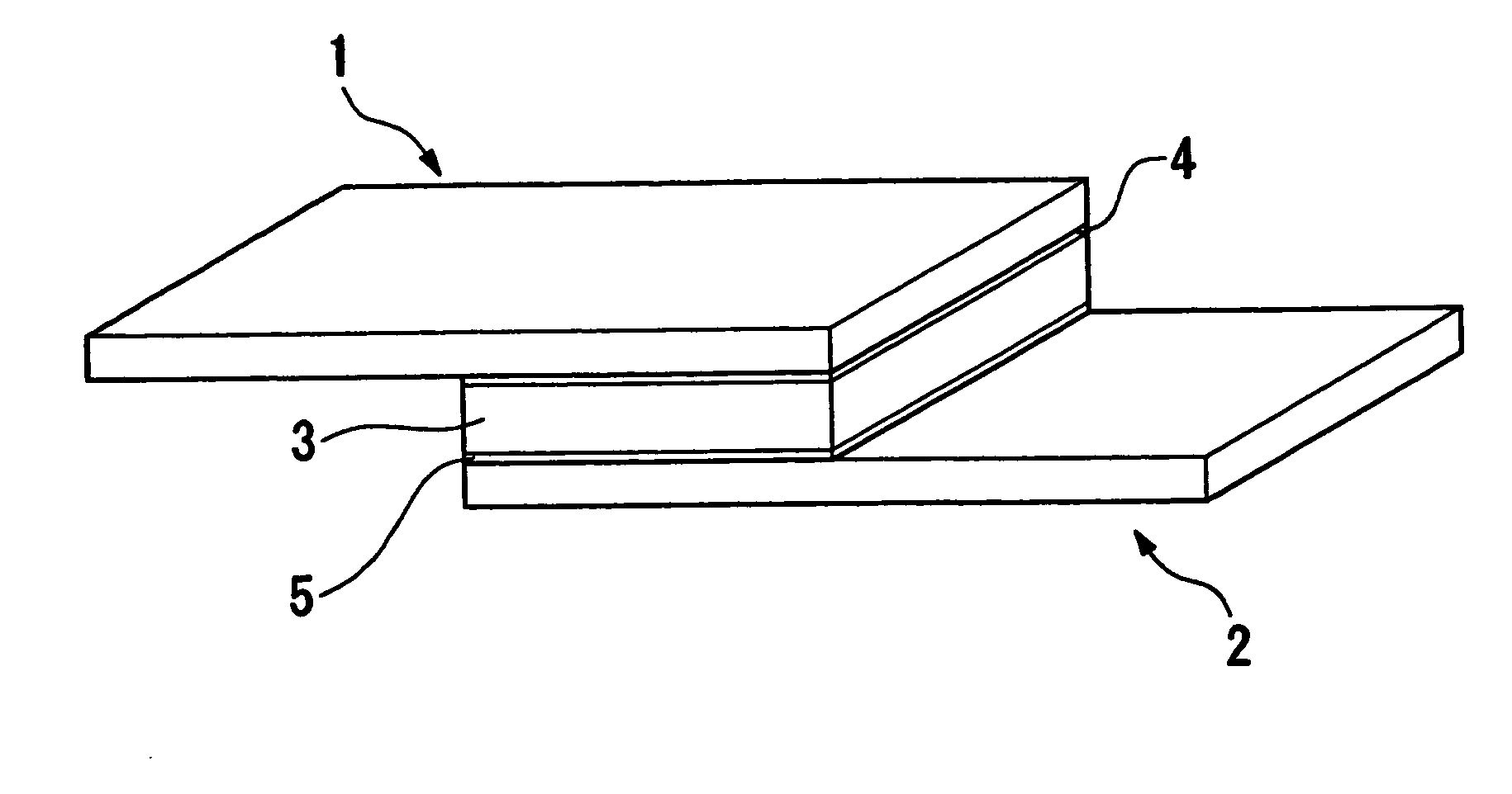
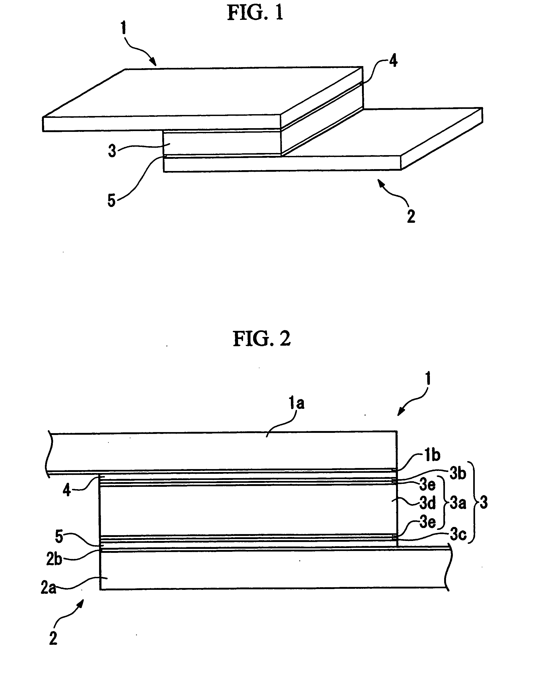
[0021]FIG. 1 and FIG. 2 show a polymeric PTC thermistor as an overcurrent protection device. This polymeric PTC thermistor comprises two electrodes 1, 2, and a conductive member 3 sandwiched between these two electrodes 1, 2. The electrodes 1, 2 and the conductive member 3 are bonded by adhesive 4, 5 having conductivity so that the two are not directly in contact with each other.

[0022] The electrode I is provided on one side surface of the conductive member 3 and the electrode 2 is provided on the other side surface of the conductive member 3. From a plane view, the electrode 1 is a rectangular sheet-form with uniform thickness and has a dual-layer structure of a nickel sheet la covered with a gold thin-film 1b. The electrode 2 also has the same shape as the electrode 1 and has a dual-layer structure of a nickel sheet 2a covered with a gold thin-film 2b.

[0023] From a plane view, the conductive member 3 is a square sheet-f...

second embodiment

[0034] Next, this invention, shown in FIG. 3, is explained.

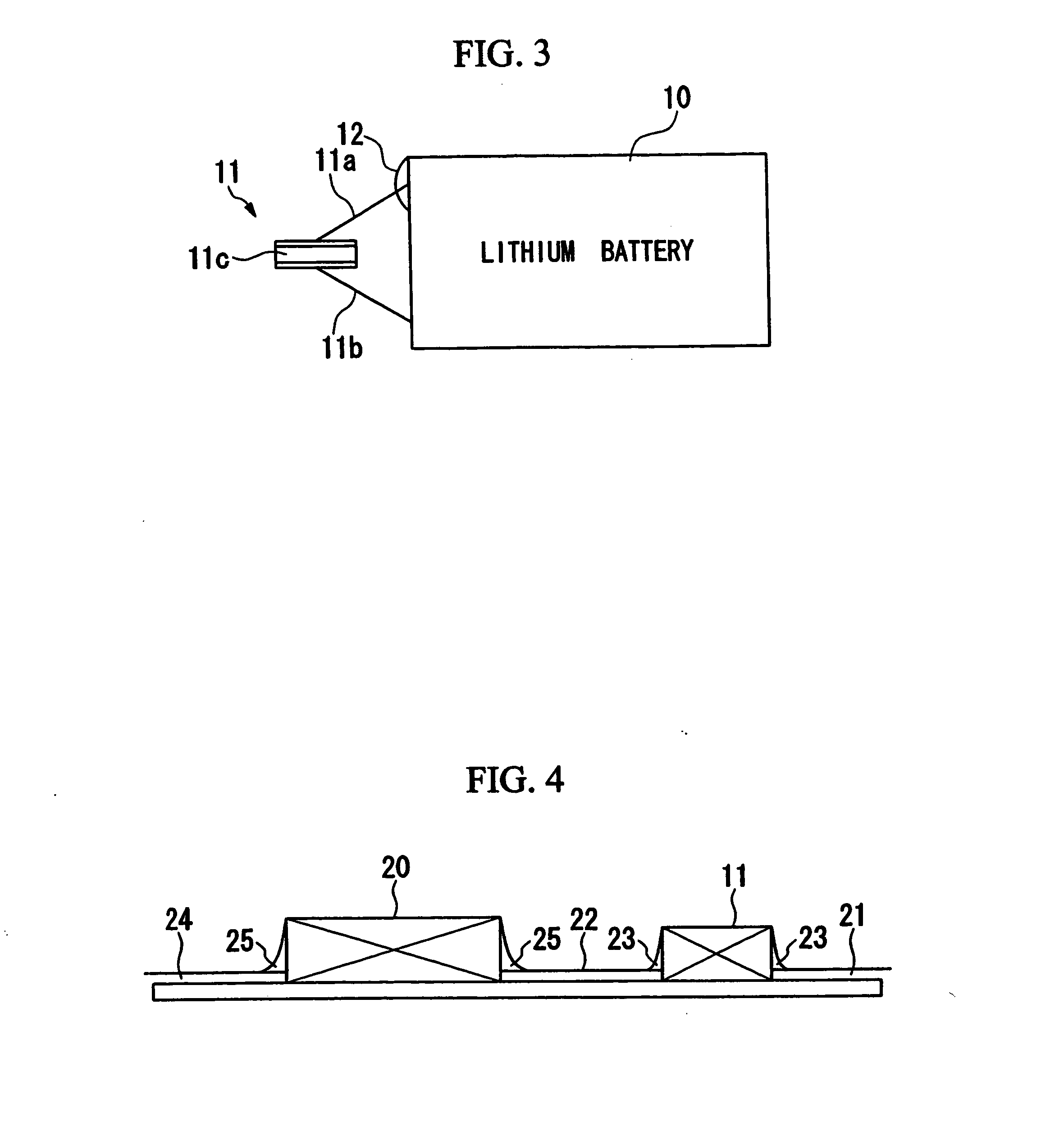
[0035]FIG. 3 shows a protection circuit for lithium battery. This protection circuit is provided with a lithium battery (component) 10 and a PTC thermistor 11. For the PTC thermistor 11, one having a conventional construction was adopted rather than the construction explained in the above first embodiment. One lead of the PTC thermistor 11 is connected to the wiring 11 a linked to the positive electrode of the lithium battery 10, and the wiring 11 a is bonded, in such a way that current will flow, to the positive electrode of the lithium battery 10 by an adhesive 12 similar to the adhesive explained in the above fist embodiment Also, the other lead of the PTC thermistor 11 is connected to the wiring 11b linked to the negative electrode of the lithium battery 10, and the wiring 11b is bonded, in such a way that current will flow, to the negative electrode of the lithium battery 10 by a bonding means such as welding or solderi...

third embodiment

[0038] Next, this invention, shown in FIG. 4, is explained. Structural elements already in explained in the embodiments above have been given the same legends and explanations have been omitted.

[0039]FIG. 4 shows a circuit constructed on a printed substrate. This circuit is provided with a capacitor (component) 20, and a PTC thermistor 11 with two electrodes, one of which is connected to an electrode of the capacitor 20. One end of the wiring 21 is soldered to one electrode of the PTC thermistor 11, and one end of the wiring 22 is soldered to the other electrode (the legend 23 is solder). The other end of the wiring 21 in connected to an unillustrated input side of the circuit. The other end of the wiring 22 is connected, in such a way that current flows, to an electrode on the capacitor 20 with an adhesive 25 similar to the adhesive explained in the above first and second embodiments. One end of the wiring 24 of bonded with an adhesive 25, in such a way that current will flow, to t...


PUM


Abstract

A PTC thermistor provided with a conductive member having PTC characteristics and two electrodes each placed in two different locations on the conductive member. The, conductive member and at least one of the two electrodes is bonded via an adhesive which has conductivity and which at the same time deteriorates in an overheated state and irreversibly increases the electrical resistance.

Description

TECHNICAL FIELD [0001] The present invention relates to a thermistor, and a circuit protection method for protecting the circuit as an overcurrent protection device or a temperature protection device. [0002] Priority is claimed on Japanese Patent Application No. 2003-178662, filed on Jun. 23, 2003, the content of which is incorporated herein by reference. BACKGROUND ART OF THE INVENTION [0003] A polymer PTC thermistor is a device which flows current, or which reduces current flow by using a positive resistance temperature characteristic, that is, a PTC (Positive Temperature Coefficient) of a conductive polymer which is varied in conductivity due to thermal expansion. In detail, it is common that in a conductive member which is composed of a conductive polymer, ceramics or the like, the conductive member is soldered to two electrodes disposed on two separate positions thereof. [0004] The conductive polymer is one of materials which compose the conductive member. The conductive polyme...

Claims


Application Information

Patent Timeline
Patent Type & Authority Applications(United States)
IPC IPC(8): H01C7/13H01C1/14H01C7/02
CPCH01C1/1406H01C7/02H05K1/0201H05K2201/10022H05K1/181H05K3/321H05K1/0293
Inventor KOYAMA, HIROYUKI
Owner TYCO ELECTRONICS RAYCHEM KK
Why Eureka
Try Eureka