

Deoxyribonucleic acid measuring apparatus and method of measuring deoxyribonucleic acid
- Summary
- Abstract
- Description
- Claims
- Application Information
AI Technical Summary
Benefits of technology
Problems solved by technology
Method used
Image

Examples
first embodiment
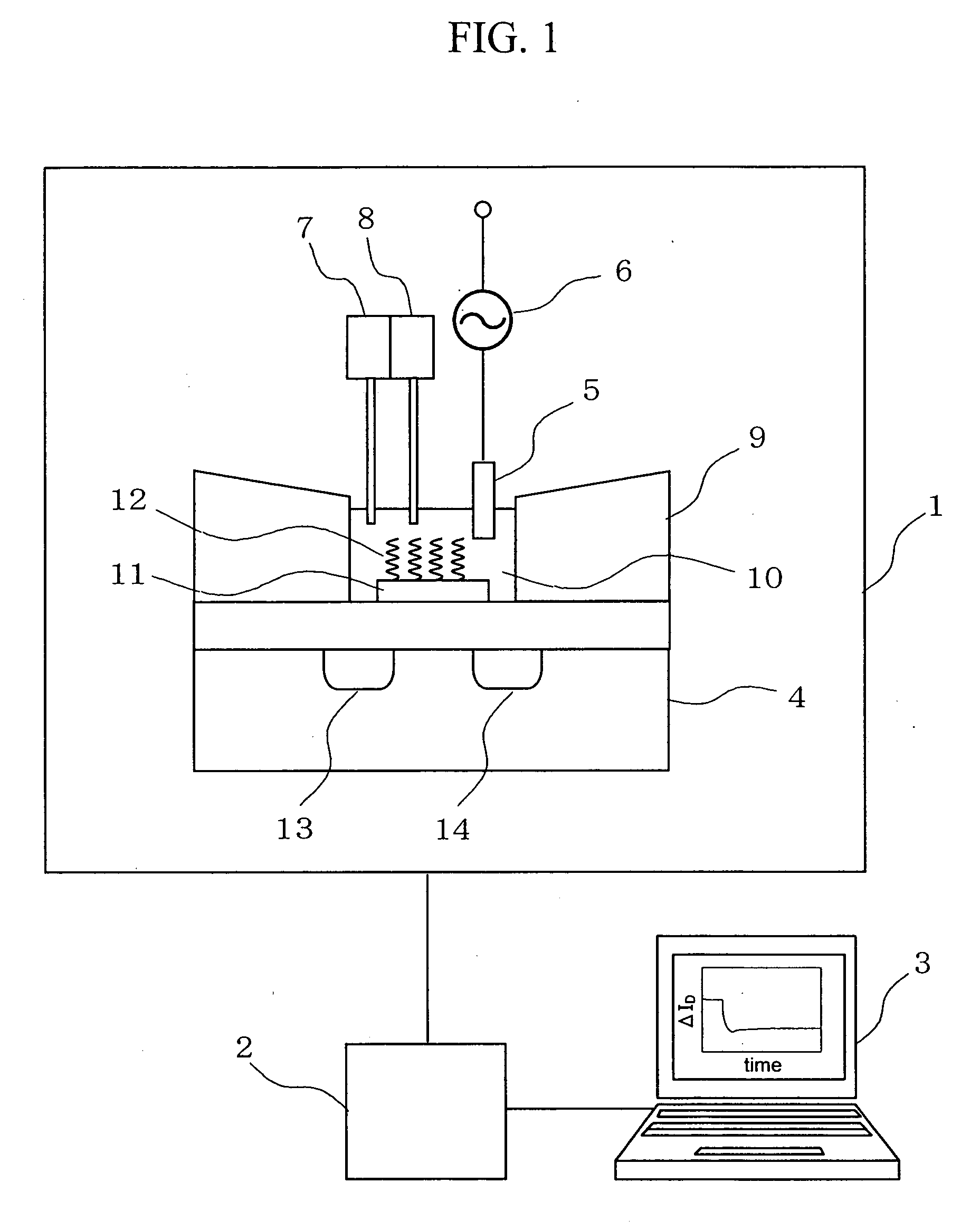
[0037]FIG. 1 is a block diagram showing a deoxyribonucleoside acid (DNA) measuring apparatus to which a DNA immobilized field effect transistor (FET) sensor according to the present invention is applied. A measuring system of this embodiment includes a measuring unit 1, a signal processing circuit 2, and a data processing device 3. The measuring unit 1 incorporates an insulated gate field effect transistor 4, a reference electrode 5, a power source 6 for applying a high-frequency voltage to the reference electrode 5, a target DNA solution injector 7, a substance solution injector 8, and a measuring cell 9. A gold electrode 11 formed on the insulated gate field effect transistor 4, DNA probes 12 immobilized onto a surface of the gold electrode 11, and the reference electrode 5 are disposed in a reactive solution 10 inside the measuring cell 9.
[0038] A measurement procedure is as follows. In the beginning, target DNA solution is injected into the reactive solution 10 inside the measur...
second embodiment
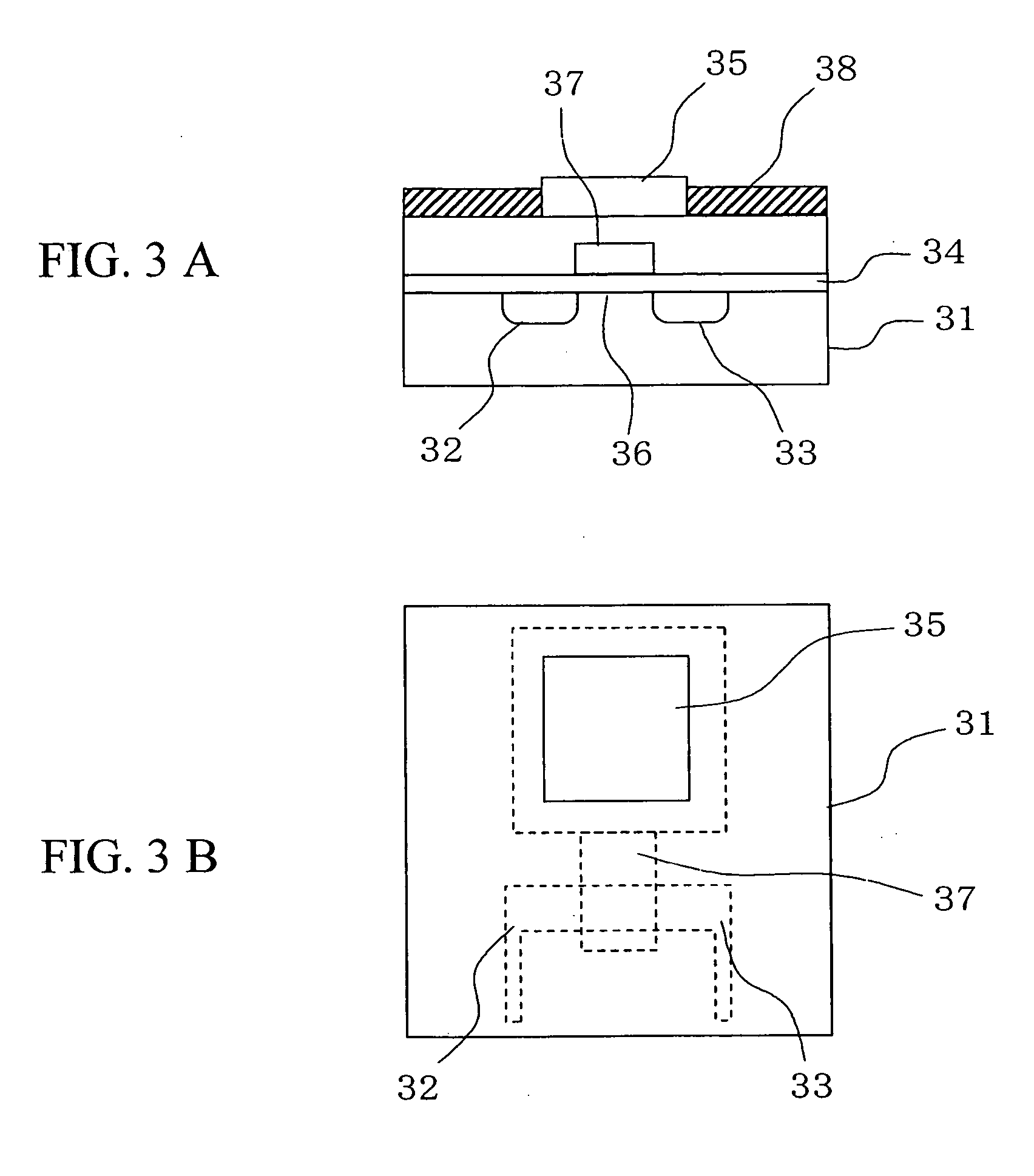
[0046] the present invention will be described below. FIG. 5 is a view showing a DNA measuring apparatus using a DNA immobilization FET sensor according to this embodiment. In an insulated gate field effect transistor 51 used in this embodiment, a source 52, a drain 53, and a gate insulator 54 are formed on a surface of a silicon substrate, while a gold electrode 55 is provided on a surface of the gate insulator between the source 52 and the drain 53. DNA probes 56 and alkanethiols 57 are immobilized on the surface of the gold electrode 55. In the actual measurement, the gold electrode 55, the DNA probes 56 as well as the alkanethiols 57 immobilized on the surface of the gold electrode 55, and a reference electrode 58 are disposed in a reactive solution 60 inside a measuring cell 59. Then, a high-frequency voltage is applied from a power source 61 to the reference electrode 58 to detect a change in electric characteristics of the insulated gate field effect transistor 51 which chang...
PUM
| Property | Measurement | Unit |
|---|---|---|
| Frequency | aaaaa | aaaaa |
| Current | aaaaa | aaaaa |
| Electrical conductor | aaaaa | aaaaa |
Abstract
Description
Claims
Application Information