System for improving the wearability of a surface and related method

a technology of wearability and wearability, applied in the direction of superimposed coating process, natural mineral layered products, manufacturing tools, etc., can solve the problems of increasing the wear of the surface, increasing the cost of manifestation, and increasing the wear of the manufacturer that works with the machining material, so as to improve the resistance to mechanical and chemical wear.

Inactive Publication Date: 2007-04-19
EIP HLDG
View PDF15 Cites 28 Cited by
  • Summary
  • Abstract
  • Description
  • Claims
  • Application Information

AI Technical Summary

Benefits of technology

[0016] The invention includes a wear system that has the characteristic of improved resistance to mechanical and chemical wear. The system includes a substrate that has a surface in which are defined three-dimensional, micro-metered, prismatic anchoring sites. The anchoring sites are characterized as hairs that are separated by spaces, thereby forming a textured surface.

Problems solved by technology

Industry realizes that the amount of wear need not be significant before its manifestation becomes quite expensive.
Any manufacturer that works with machining materials is exposed to the problems of wear.
Because certain materials are difficult to machine, cutting speeds are reduced.
However, their extremely high cost (compared to tungsten carbide, ceramics and cermets) limits their use in many cases, especially when the least expensive of these materials (tungsten carbide) can be enhanced with alloying and coatings (TiN, TiCN, Al2O3), thereby reducing its tendency to chemically dissolve into the chip and workpiece at high temperatures.
Unfortunately, developments in these substrate materials and coatings are quite mature and may offer little more than incremental improvements in the near future.
One problem of prior approaches is the very high temperatures experienced by the cutting tool.
PVD coatings have to be thinner since their production process induces significant internal stress that causes flaking of thicker coatings under only small applied loads.
CVD coatings, though much thicker, are limited in thickness due to the same internal stresses as for PVD coatings, as well as ones that develop due to the coefficient of thermal expansion mismatch across the large rake face surface and the delamination that occurs as the two sides of the interface expand at different rates.
Either way, these coatings are thin, and often wear through rather quickly.
However, their abrasion resistance is virtually gone once wear-through has occurred.
While diamond and CBN possess good abrasion / heat resistance, they are limited in their use (e.g., diamond cannot be used in contact with ferrous alloys due to a high propensity to dissolve in the iron), not to mention they are expensive relative to tungsten carbide.
Machining of CGI is further hampered in continuous cutting due to its relatively high ductility (compared to gray iron), causing it to create higher temperatures on the cutting tool (Reuter and Schulz, 1999).
Polymer-matrix composites along with metal-matrix composites (used significantly in modern aircraft and other lightweight applications) cause wear almost solely through abrasion (Yanming and Zehua, 2000).
CVD coatings can be made thicker, but as a conformal deposition process, films can build up excessively on surface discontinuities and sharp curvature surfaces, especially in high pressure processing utilized to enhance the deposition rate.

Method used


Image

  • System for improving the wearability of a surface and related method
  • System for improving the wearability of a surface and related method
  • System for improving the wearability of a surface and related method

Examples


Embodiment Construction

)

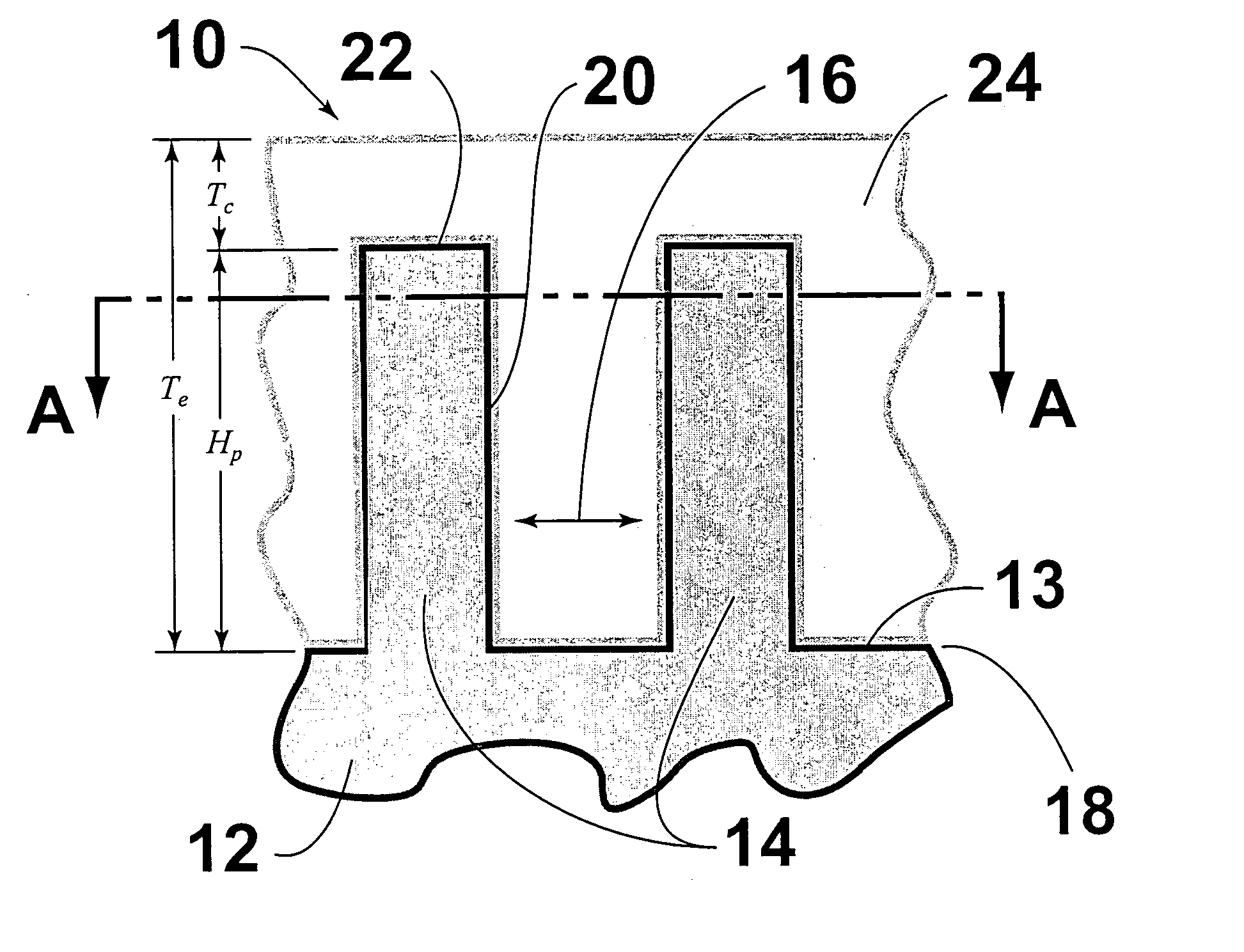
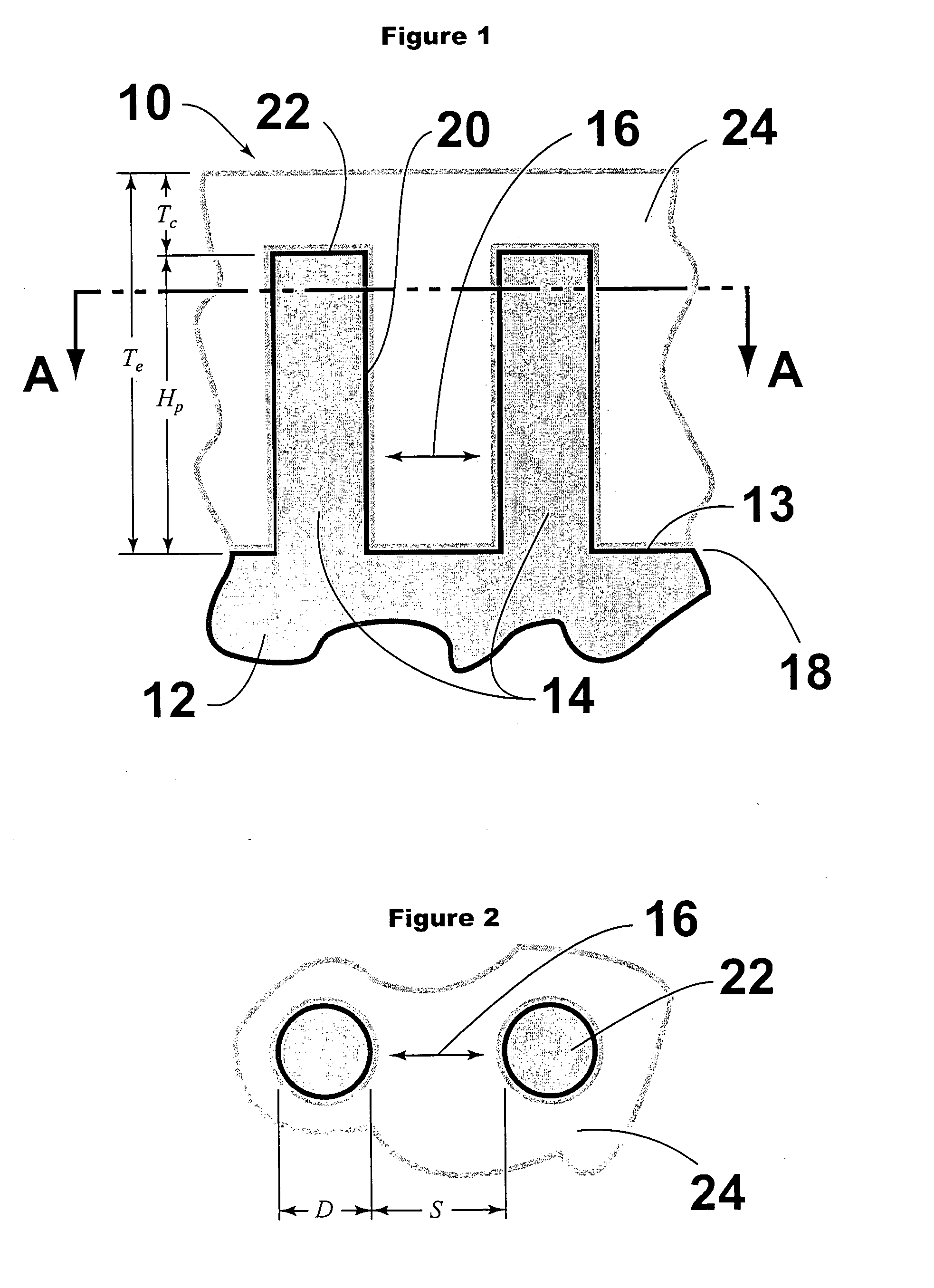
[0029] Turning first to FIGS. 1-3, there is depicted a wear system 10 that has the characteristic of improved resistance to mechanical and chemical wear. The system includes a substrate 12 which has a surface 13 in which are defined three-dimensional, micro-metered, prismatic anchoring sites. As used herein, the term “micro-metered” refers to anchoring sites wherein the distance D (FIG. 2) is preferably about 25 microns and the spacing S (FIG. 2) between adjacent anchoring site(s) in some applications is preferably about 50 microns.

[0030] As best shown in FIG. 1, the anchoring sites are characterized as hairs 14 that are separated by at least some spaces 16, thereby forming a textured surface 18.

[0031] A coating 24 is applied to the textured surface 18. The coating 24 has substantially conforming three-dimensional features that mate with at least some of the hairs 14 of the anchoring sites. Upon solidification, the coating becomes hardened and is relatively immune from delaminati...


PUM

PropertyMeasurementUnit
distanceaaaaaaaaaa
thickaaaaaaaaaa
thickaaaaaaaaaa

Abstract

A wear surface system and method for preparing same. The wear surface system 10 has a substrate 12 with a surface 13 in which is defined three-dimensional, micro-metered prismatic anchoring sites 14. The sites include hairs that are separated by at least some spaces 16. To the textured surface 18 is applied a coating 24. The coating has substantially conforming three-dimensional features that mate with at least some of the anchoring sites. Upon solidification, the coating becomes hardened and is relatively immune from delamination due to internal and externally applied stresses during exposure to normal wear conditions. One method for improving the wearability of a surface comprises the steps of (1) providing a substrate; (2) texturizing its surface so that it is at least partially imbued with a three-dimensional, micro-metered, prismatic set of anchoring sites; and (3) coating at least a part of the textured surface with a mating coating that becomes hardened upon solidification.

Description

BACKGROUND OF THE INVENTION [0001] 1. Field of the Invention [0002] The invention relates to a system and method for improving the wearability of surfaces that are exposed to wear conditions during their working life. [0003] 2. Background Art [0004] The wear phenomenon is generally a physical form of material degradation in that it involves the removal of surface material as a result of mechanical and / or chemical action. Industry realizes that the amount of wear need not be significant before its manifestation becomes quite expensive. For instance, a car can be considered “worn out” following the loss of only a minor amount of material from critical surfaces that are in sliding contact. [0005] It is known that there are various forms of wear: (1) adhesive wear—this occurs when two glissile surfaces slide over each other and debris is removed from one surface which adheres to the other; (2) abrasive wear—this happens when a hard, rough surface interacts with a softer surface, thereby...

Claims


Application Information

Patent Timeline
Patent Type & Authority Applications(United States)
IPC IPC(8): B05D3/00B32B15/04B32B9/00
CPCB23B27/146B23B2228/10C23C4/02C23C28/044Y10T428/24479Y10T428/24612Y10T428/24521Y10T428/30C23C28/046
Inventor ENDRES, WILLIAM J.
Owner EIP HLDG
Why Eureka
Try Eureka