
Carbon material for battery electrode and production method and use thereof

a technology of carbon material and battery electrode, which is applied in the direction of graphite, non-aqueous electrolyte accumulator electrode, cell components, etc., can solve the problems of increasing irreversible capacity, reducing coulombic efficiency (i.e., initial discharge capacity/initial charge capacity), and serious practical problems such as low mass productivity, low capacity, and low cost. , to achieve the effect of large discharge capacity, less deformation/orientation, and excellent coulomb

Inactive Publication Date: 2007-04-26
SHOWA DENKO KK
View PDF31 Cites 36 Cited by
  • Summary
  • Abstract
  • Description
  • Claims
  • Application Information

AI Technical Summary

Benefits of technology

[0007] Thus, an object of the present invention is to prepare carbon particles having a particle size of several tens of nm to several hundreds of μm, each particle having a virtually homogeneous structure from the surface to the center of the particle by compounding and integrating a carbonaceous particle (particularly natural graphite particles) serving as a core material with other carbon materials, and thereby provide a battery electrode material which undergoes less deformation / orientation due to application of pressure, has a large discharge capacity, exhibits excellent coulombic efficiency and cycle characteristics, is employable under large current conditions, and has small irreversible capacity.
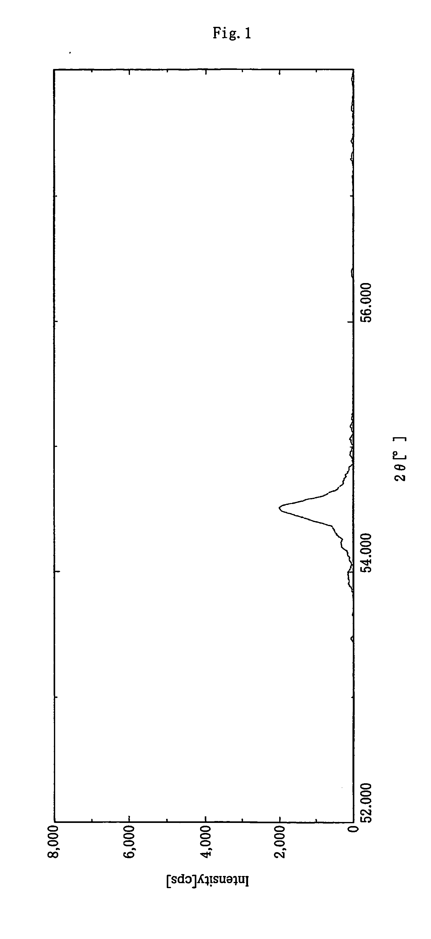
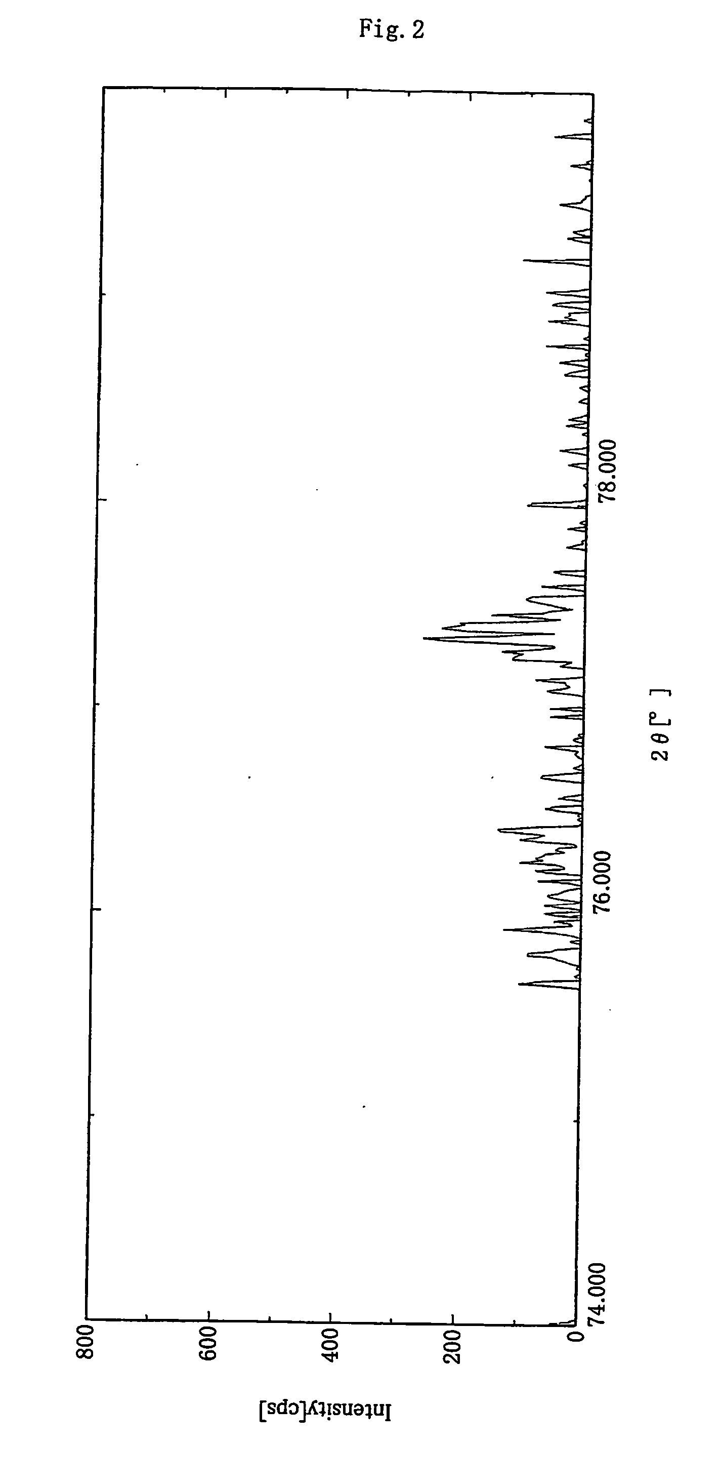
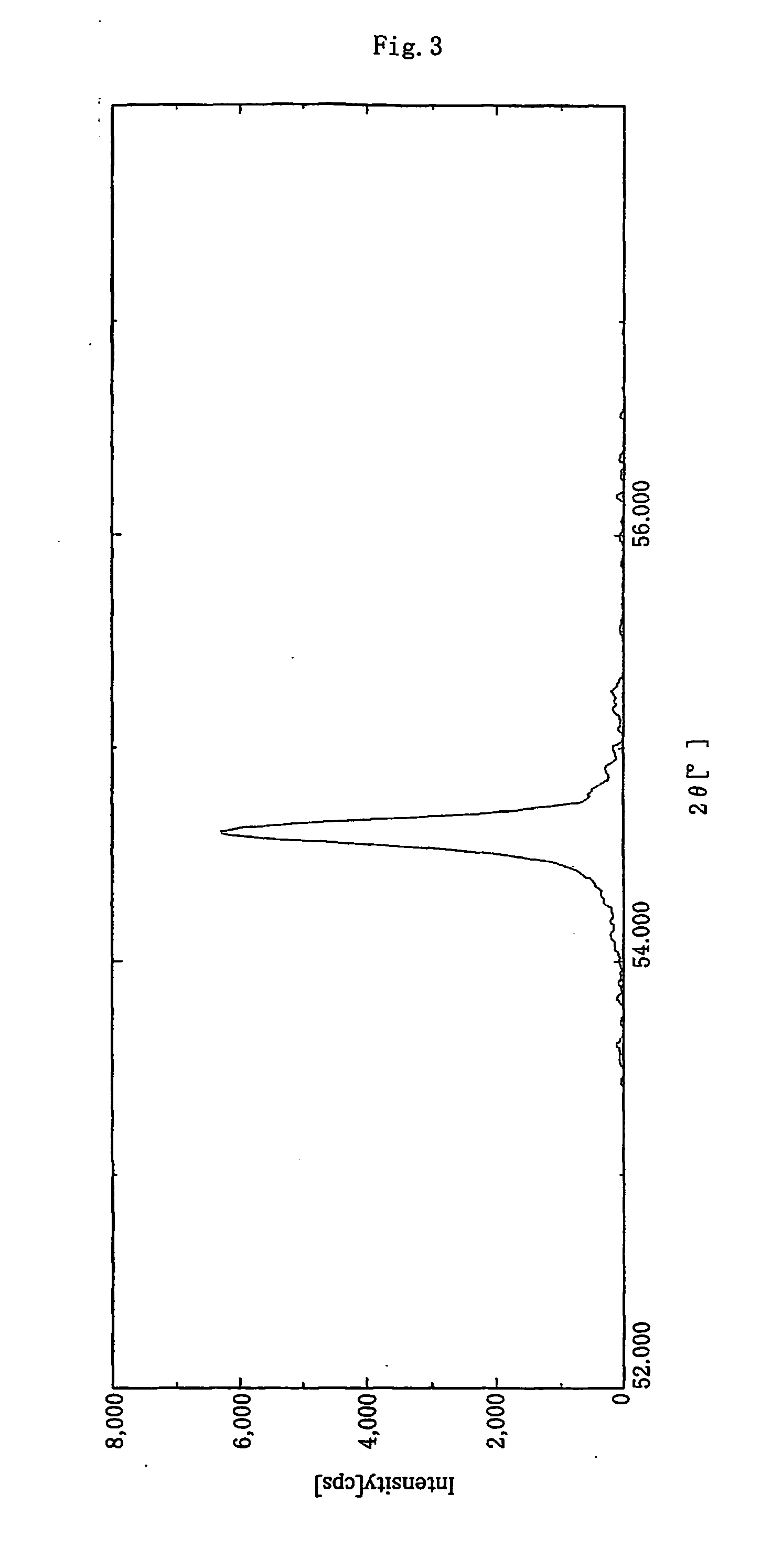
[0008] The present inventors have carried out extensive studies in order to solve the aforementioned problems involved in the related art, and have found that carbon particles, each particle having a virtually homogeneous structure from the surface to the center thereof, can be produced by uniformly incorporating a specific amount of an organic substance into high-crystallinity graphite particles having a specific particle size, through impregnation or compounding, and by carbonizing the organic substance at high temperature, and that when the ratio of peak intensity attributed to a (110) plane to that attributed to a (004) plane, the ratio being determined through X-ray diffraction spectroscopic analysis of a specific press-molded compact containing the carbon particles, reaches a specific value (≧0.1), a battery electrode material which undergoes less pressure-induced deformation, exhibits low shape selectivity of particles (after pressure has been applied thereto), exhibits excellent coulombic efficiency, cycle characteristics, large-current characteristics, and has small irreversible capacity can be produced without impairing a characteristically high discharge capacity of high-crystallinity graphite particles. The present invention has been accomplished on the basis of these findings.

Problems solved by technology

As the crystallinity of graphite increases, there arise problems of decrease in coulombic efficiency (i.e., initial discharge capacity / initial charge capacity) and increase in irreversible capacity, which are conceivably caused by decomposition of an electrolyte (see J. Electrochem. Soc., Vol. 117, 1970, p.
However, the technique disclosed in EP No. 520667 where an amorphous carbon layer is formed on a high-crystallinity carbon material member through CVD (chemical vapor deposition, or vapor phase deposition) involves serious practical problems of high cost, low mass productivity and the like.
In addition, a negative electrode material coated with an amorphous carbon layer, a so-called double-layer carbon material, still has drawbacks stemming from the amorphous carbon layer; e.g., low capacity and low coulombic efficiency.
Although JP-A-11-310405 and other documents disclose a technique in which an amorphous carbon layer is formed through a liquid-phase carbon formation method, which is advantageous in terms of cost and mass productivity, the aforementioned drawbacks involved in the amorphous carbon layer have not yet been resolved.
Such deformation / orientation occurs during fabrication of an electrode (i.e., application of paste or pressing), thereby raising problems; falling of the fabricated electrode, poor impregnation performance with respect to electrolyte, and deterioration of current-load characteristics and cycle characteristics.
These problems have not been solved completely even in the aforementioned techniques where the carbon member is coated with an amorphous carbon layer.

Method used


Image

  • Carbon material for battery electrode and production method and use thereof
  • Carbon material for battery electrode and production method and use thereof
  • Carbon material for battery electrode and production method and use thereof

Examples


example 1

[0150] As a graphite material serving as core material, there was employed carbonaceous powder (100 g) having a laser diffraction mean particle size of 20 μm, a mean roundness of 0.88, and an area ratio of 80:20 for crystalline carbon-portion / amorphous carbon portion as determined in a bright field image observed under a transmission electron microscope. The graphite material had a BET specific surface area of 5.6 m2 / g, and a C0 of 0.6710 nm, as measured through X-ray diffraction spectroscopy. By a laser Raman spectrum of the surface of the graphite material, the peak intensity ratio for the peak intensity at 1,360 cm−1 / the peak intensity at 1,580 cm−1 was 0.21.

[0151] The graphite material (300 parts by mass), phenol (398 parts by mass), 37% formalin (466 parts by mass), hexamethylenetetramine (38 parts by mass) serving as a reaction catalyst, and water (385 parts by mass) were fed into a reaction container. The mixture was stirred at 60 rpm for 20 minutes. Air was evacuated from ...

example 2

[0155] As a graphite material serving as a core material, there was employed a carbonaceous powder (100 g) prepared by processing flake graphite material having a mean particle size of 5 μm with a hybridizer (product of Nara Machinery Co., Ltd.) for rounding the particles, and having a laser diffraction mean particle size of 15 μm, a mean roundness of 0.86, and an area ratio of 90:10 for crystalline carbon-portion / amorphous carbon portion as determined in a bright field image observed under a transmission electron microscope. The graphite particles had a BET specific surface area of 5.3 m2 / g, and a C0 of 0.6712 nm, as measured through X-ray diffraction spectroscopy. By a laser Raman spectrum of the surface of the graphite material, the peak intensity ratio for the peak intensity at 1,360 cm−1 the peak intensity at 1,580 cm−1 was found to be 0.20. The graphite powder was further treated in a manner similar to that of Example 1.

[0156] The orientation characteristics of the powders an...

example 3

[0158] As a graphite material serving as a core material, there was employed a carbonaceous powder (100 g) that had a laser diffraction mean particle size of 15 μm, a mean roundness of 0.88, and an area ratio 80:20 for crystalline carbon portion / amorphous portion as determined in a bright field image observed under a transmission electron microscope. The graphite particles had a BET specific surface area of 5.6 m2 / g, and a C0 of 0.6716 nm, as measured through X-ray diffraction spectroscopy. By a laser Raman spectrum of the surface of the graphite material, the peak intensity ratio for the peak intensity at 1,360 cm−1 the peak intensity at 1,580 cm−1 was found to be 0.22.

[0159] An ethanol solution of phenolic resin monomers (55 parts by mass in terms of resin solid) and ethanol (50 parts by mass) were mixed and stirred until the monomers were completely dissolved in water. The thus-obtained solution was added to the aforementioned carbonaceous powder so that the phenolic resin solid...


PUM

PropertyMeasurementUnit
crystallite sizeaaaaaaaaaa

Abstract

The invention provides a carbon material for a battery electrode, which comprises a carbon powder material as a composite of carbonaceous particles and an a carbon material derived from an organic compound prepared by allowing the organic compound serving as a polymer source material to deposit onto and / or permeate into the carbonaceous particles to thereby polymerize the polymer material and then heating at 1,800 to 3,300° C., and which has an intensity ratio of 0.1 or more for peak intensity attributed to a (110) plane to peak intensity attributed to a (004) plane determined through X-ray diffraction spectroscopic analysis on a mixture of the carbon material and a binder resin when pressed at 103 kg / cm2 or higher. The carbon material which undergoes less deformation / orientation due to application of pressure, has high discharge capacity and small irreversible capacity and exhibiting excellent coulombic efficiency, cycle characteristics and leakage-current load characteristics.

Description

CROSS-REFERENCE TO RELATED APPLICATIONS [0001] This is an application filed pursuant to 35 U.S.C. Section 111(a) with claiming the benefit of U.S. provisional application Ser. No. 60 / 518,660 filed Nov. 12, 2003 under the provision of 35 U.S.C. 111(b), pursuant to 35 U.S.C. Section 119(e) (1).TECHNICAL FIELD [0002] The present invention relates to an electrode material for a battery, particularly for a non-aqueous electrolytic solution secondary battery, having a high charge / discharge capacity and exhibiting excellent charge / discharge cycle characteristics and large-current load characteristics, to an electrode employing the material, and to a non-aqueous electrolytic solution secondary battery employing the material. More particularly, the invention relates to a negative electrode material for a lithium secondary battery, to a negative electrode employing the negative electrode material, and to a lithium secondary battery employing the negative electrode material. BACKGROUND ART [00...

Claims


Application Information

Patent Timeline
Patent Type & Authority Applications(United States)
IPC IPC(8): H01M4/58C01B31/04H01M4/133H01M4/1393H01M4/583H01M4/587H01M10/0525H01M10/36
CPCH01M4/133H01M4/1393H01M10/0525H01M4/587H01M4/625H01M4/583Y02E60/10C01B32/21
Inventor SOTOWA, CHIAKITAKEUCHI, MASATAKASUDOH, AKINORI
Owner SHOWA DENKO KK
Learn More