Set of processes for removing impurities from a silcon production facility

a technology of silcon production and process, applied in the direction of separation process, silicon compound, energy input, etc., can solve the problems of proposed distillation scheme failure, ingle distilling all of recycled sicl, etc., and achieves the effect of not required or optimal, and not providing for solid aluminum trichlorid

Inactive Publication Date: 2007-05-03
XSI INT A BRITISH VIRGIN ISLANDS +1
View PDF7 Cites 25 Cited by
  • Summary
  • Abstract
  • Description
  • Claims
  • Application Information

AI Technical Summary

Problems solved by technology

The disposal of the byproduct STC was generally recognized as a problem and various methods arose to convert it back to TCS or to silica and HCl.
He does not provide for the solid aluminum trichloride and hence his proposed distillation scheme would fail.
Ingle also distills all of the recycled SiCl4 which is not required or optimal.
Breneman states in column 6 line 44“All of the byproduct materials are recycled for further use, . . .” The purity levels required are very high, often parts per billion or higher which are very difficult to detect directly and consequently may require use of redundant purification steps.
A major problem in the prior art is that the purification is primarily of the material typically SiHCl3 or SiH4 or SiHBr3, used for the final silicon deposition.
Not surprisingly some of the impurities found in the TCS, TBS or SiH4 are very close chemically and in physical properties to the pure material and the purification required is very high which requires significant loss of product to remove the impurities.
Thus distillation columns to remove these impurities tend to be large and expensive to run.
A further problem is that there is no effort to deliberately remove impurities as solids from the effluent gas stream from the reactor.
A yet further problem is the...

Method used


Image

  • Set of processes for removing impurities from a silcon production facility
  • Set of processes for removing impurities from a silcon production facility
  • Set of processes for removing impurities from a silcon production facility

Examples


examples

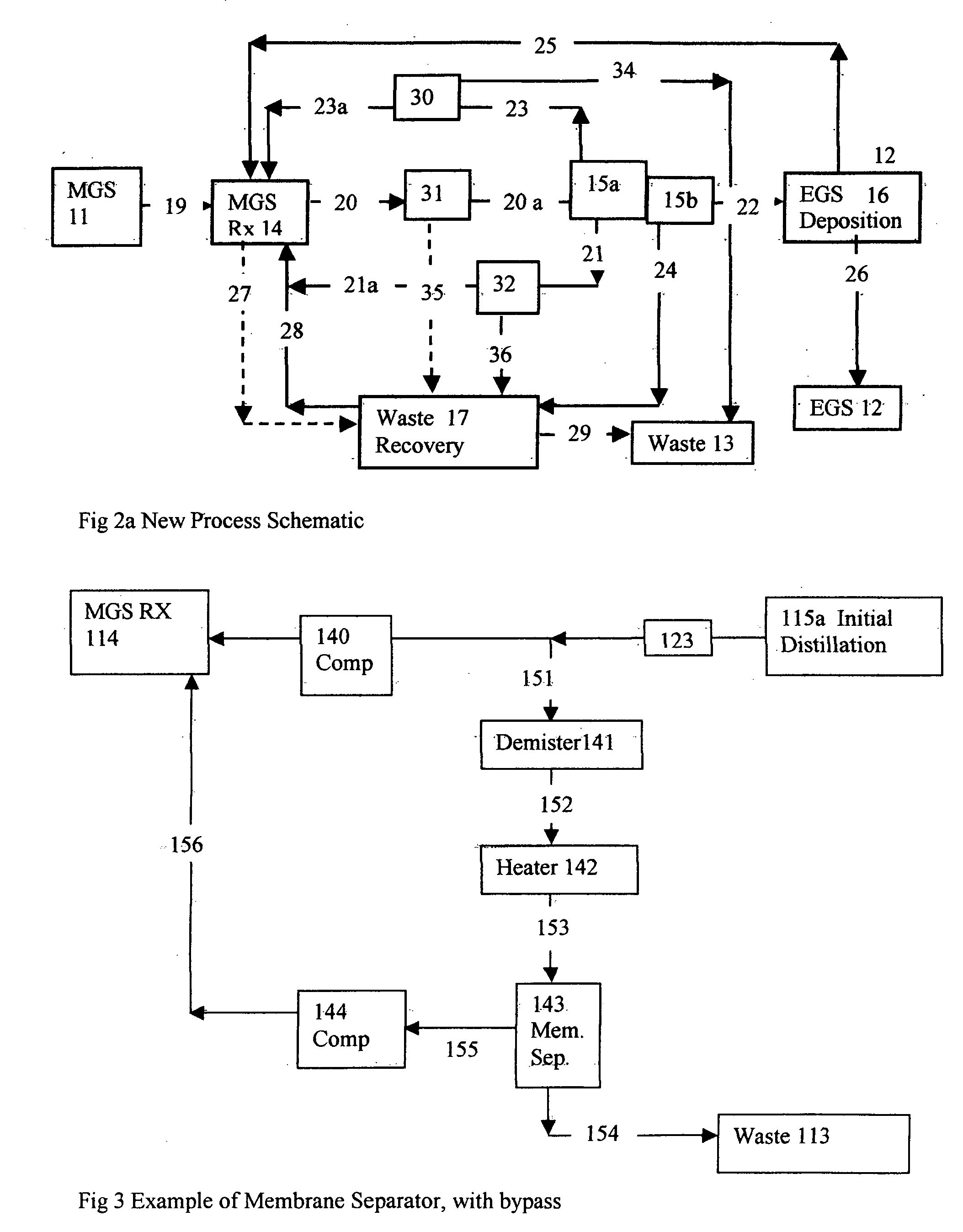
[0046] 1A gas stream is to be produced from a degassing column at a composition of 3.5 SCFH H2SiCl2;2.4 SCFH HSiCl3;51.5 HCl; 5407.5 H2;095 CH4 and 0.005 SCFH PH3 for a total of 5465 SCFH at a pressure of 470 psig and a temperature of 125 F(51° C.). The gas will be demisted in a demisting pad and reheated to 140 F(60° C.) and reduced in pressure to 400 psig then passed through a separator using a polysulfone membrane. The low-pressure stream will be produced at 25 psig with a composition of 0.1 SCFH H2SiCl2;0.1 SCFH HSiCl3;45 HCl; 4865 H2;005 CH4 and 0.001 SCFH PH3 for a total of 4910 SCFH (approx), the high pressure stream will be produced at 380 psig with a composition of 3.4 SCFH H2SiCl2;2.3 SCFH HSiCl3;6.5 HCl; 542.5 H2; 09 CH4 and 0.004 SCFH PH3 for a total of 555 SCFH (approx). Thus about 90% of the hydrogen and hydrogen chloride are recovered to the low-pressure stream and 90% of the methane and 80% of the phosphine are recovered to the high-pressure stream along with most of...


PUM

PropertyMeasurementUnit
Temperatureaaaaaaaaaa

Abstract

A set of three low cost processes for removing boron, phosphorus, carbon and other metal and nonmetal impurities during the process of converting metallurgical grade silicon to electronic grade silicon. One process removes boron by using one or more high temperature solids removal devices to remove solid titanium diboride from a halosilane reactor effluent stream where the high temperature is preferably greater than 200 C., more preferably greater than 300 C. and most preferably greater than 400 C. A second process removes carbon as methane and phosphorus as phosphine by means of a membrane separator which processes all or part of a hydrogen recycle stream to recover hydrogen while rejecting methane and phosphine. A third process separates a high boiling halosilane stream into a large low impurity stream and one or more small high impurity streams some of which can be sent for halogen recovery.

Description

CROSS REFERENCE TO RELATED APPLICATIONS [0001] Not Applicable STATEMENT REGARDING FEDERALLY SPONSORED RESEARCH OR DEVELOPMENT [0002] Not Applicable DESCRIPTION OF ATTACHED APPENDIX [0003] Not Applicable BACKGROUND OF THE INVENTION [0004] This invention relates generally to the field of high purity silicon production and within that field to the conversion of metallurgical grade silicon to electronic grade silicon and yet more specifically to a set of three processes for removing impurities from a silicon production facility. One or more of the processes may be used to prevent buildup of impurities in recycle streams and to provide a purer and more stable feedstock to the final purification steps of the standard distillation techniques commonly used to purify a high purity silicon containing gas, which is then used to produce high quality silicon in a deposition reactor, The locations where the impurities are removed are called sinks and the locations where they enter are called sour...

Claims


Application Information

Patent Timeline
IPC IPC(8): B01D46/00
CPCB01D53/002B01D53/229B01D53/75B01D2257/204B01D2257/206B01D2258/0216C01B33/021C01B33/027C01B33/03C01B33/033C01B33/035C01B33/037C01B33/039C01B33/10778Y02P20/129Y02P20/151
Inventor LORD, STEPHEN MICHAEL
Owner XSI INT A BRITISH VIRGIN ISLANDS
Why Eureka
Try Eureka