Grinding wheel for roll grinding application and method of roll grinding thereof

a technology of grinding wheel and rolling pin, which is applied in the field of grinding wheel, can solve the problems of requiring periodic re-shaping, and affecting the quality of the finished product, and achieves the effect of constant speed ratio

Active Publication Date: 2007-05-03
DIAMOND INNOVATIONS INC
View PDF39 Cites 27 Cited by
  • Summary
  • Abstract
  • Description
  • Claims
  • Application Information

AI Technical Summary

Benefits of technology

[0018] The present invention is directed to solving one or more of the problems described above. Embodiments of the invention include an improved grinding wheel and a simplified grinding method to grind a wide variety of ferrous roll materials (e.g., iron and steel alloys) and roll shapes used in hot and cold strip mills. In an embodiment, the grinding wheel is comprised of cubic boron nitride (CBN) in a bond system, having an extended grinding life such that the ratio TT / WWC may be significantly greater than 10 and the roll exhibits no substantial visual feed marks and chatter marks. In another embodiment, a method of applying the CBN grinding wheel such that a minimum grind amount less than 0.2 mm is removed from the worn roll diameter to achieve the desired geometrical and visual specification of the machined roll. In another embodiment of the invention, a method of applying a CBN grinding wheel to grind rolls without chatter and feed marks permits varying the grinding wheel speed and / or the roll speed without monitoring the vibration levels, and not having to maintain a constant speed ratio.

Problems solved by technology

In rolling operations, the rolls undergo considerable wear and changes in surface quality and thus require periodic re-shaping by machining or grinding, i.e., “roll grinding,” to bring the roll back to the required geometric tolerances while leaving the surface free of feed lines, chatter marks and surface irregularities such as scratch marks and / or thermal degradation of the roll surface.
The challenge with both of these methods is to restore the roll to its correct profile geometry with minimum stock removal and without visible feed marks, visible chatter marks or surface irregularities.
Both feed marks and chatter marks are undesirable in the roll, as they affect the durability of the roll in service and produce an undesirable surface quality in the finished product.
Surface irregularities in the roll are associated with either a scratch mark and / or thermal degradation of the working surface of the roll following grinding.
Thermal degradation of the roll surface is caused by excessive heat in the grinding process resulting in a change in the microstructure of the roll material at or near the ground surface and / or sometimes resulting in cracks in the roll.
Inorganic bonded or vitrified or ceramic bonded abrasive wheels have not been successful in roll grinding applications compared to organic resin bonded wheels, because the former has a low impact resistance and low chatter resistance compared to the latter.
Another problem associated with the vitrified bonded conventional wheel system is that its brittle nature causes the wheel edge to break down during the grinding process, resulting in scratch marks and surface irregularities in the work roll.
However, even with these improved grinding wheels the rate of grinding wheel wear is still quite large in grinding steel rolls, that continuous radial wheel wear compensation (WWC) is employed during the grind cycle to meet geometrical taper tolerances (TT) in the roll.
The requirement of WWC in roll grinding dictates the need for sophisticated machine controls as well as added complexity to the grinding cycle.
There is a second disadvantage with the grinding wheels employing conventional abrasives of the prior art.
These additional grinding passes result in the removal of expensive roll material, leading to a reduction in the useful work roll life.
The third disadvantage of corrective grinding passes is increased cycle time, thus reducing the productivity of the process.
Loss of productive time also occurs due to frequent wheel changes that result from accelerated wear of the organic resin bonded wheels.
Yet a fourth disadvantage faced with conventional abrasive wheels is that the useful wheel diameter typically decreases from 36-24 inches (914-610 mm) over the life of the wheel, the compensation for which can result in a large cantilever action of the grinding spindle head.
The continuous increase in cantilever action results in continually changing stiffness of the grinding system, causing inconsistencies in the roll grinding process.
As the rates of grinding wheel wear are not the same for the two members of different bonding systems, profile errors, chatter and scratch marks may frequently be experienced in grinding the roll.
Since the wear on the work roll in the mill operation is not always uniform, it can be very challenging when the work roll wear is large (in excess of 0.010 mm) as non-uniform contact between the cup wheel face and the roll surface develops.
This results in uneven wheel wear, affecting the cutting ability or the sharpness of the wheel along its working face, causing uneven stock removal in the work roll along its axial length and resulting in profile errors and chatter in the process.
A limiting factor of the cup face wheel design, however, is that it can present considerable challenge and difficulty in keeping the ratio TT / WWC greater than 10 when grinding rolls of various shapes such as a convex crown, concave crown or a continuous numerical profile along the axis of the roll.
Therefore, grinding wheel article specifications and wheel manufacturing methods used for making a cup face planar disk wheel (Type 6A2) design cannot be translated to making a Type1 grinding wheel as their application methods are significantly different.
This method, however requires that the speed ratio between the revolution speed of the grinding wheel and the revolution speed of the roll be kept constant, which adds complexity in grinding a good quality roll.

Method used


Image

  • Grinding wheel for roll grinding application and method of roll grinding thereof
  • Grinding wheel for roll grinding application and method of roll grinding thereof
  • Grinding wheel for roll grinding application and method of roll grinding thereof

Examples


example 1

Grinding Performance of Iron Rolls

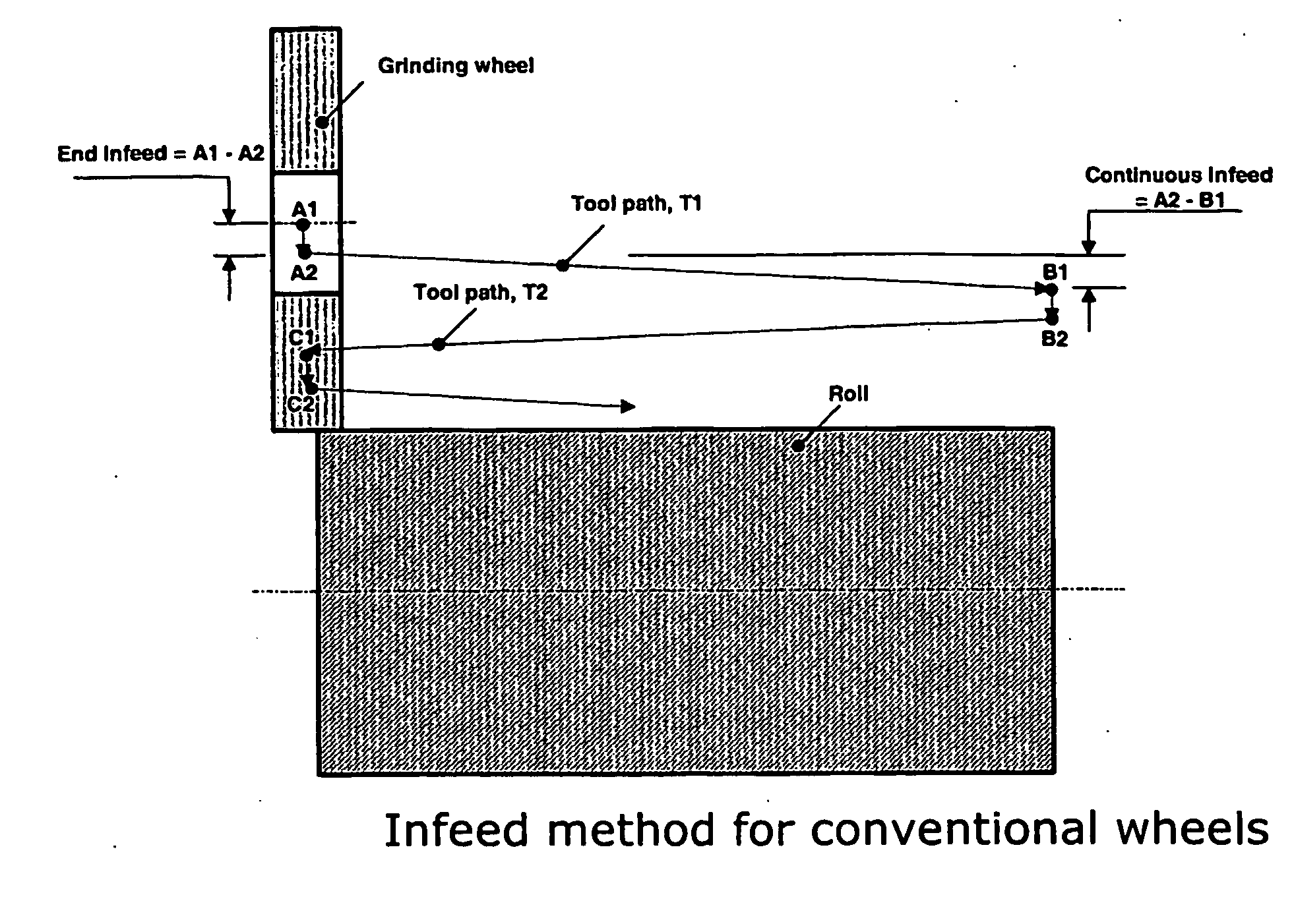
[0096] In this example, the roll grinding comparison tests are conducted on a 100HP Waldrich Siegen CNC roll grinding machine wherein the grinding wheel rotational axis is substantially parallel to the roll rotational axis, such that the angle is less than about 25 degrees. The dimensions of the iron roll are 760 D×1850 L, mm. A synthetic water soluble coolant at 5V % concentration is applied during grinding. The coolant flow rate and pressure conditions are the same for the conventional wheel and the vitrified CBN wheel in this evaluation. The hardened iron rolls have a radial wear amount of 0.23 mm that has to be corrected in the grinding operation such that the taper tolerance is less than 0.025 mm and profile tolerance is less than 0.025 mm. The grinding conditions for the comparative conventional wheel and the vitrified CBN wheel are nearly equivalent for wheel speed, traverse rate, work speed and depth of cut per pass. The grinding results ar...

example 2

Grinding Performance of forged HSS Rolls

[0099] In this example, the same wheels in Example 1 are used to grind a forged HSS work roll having a complex polynomial profile along the axis of the roll.

[0100] The wheels are not trued and are continued in the same condition after grinding the hardened iron rolls on the same grinding machine. The HSS work rolls have an initial radial wear of 0.030 mm and have to be ground such that the taper and profile shape tolerances are less than 0.025 mm. The grinding conditions in terms of the wheel speed, work speed, traverse rate and depth of cut are equivalent for both the comparative wheel and the vitrified CBN wheel. The dimensions of HSS roll used are 760.5 D×1850 L, mm.

[0101] The grinding conditions and results are given below in Table 3.

TABLE 3Comparative wheelVitrified CBN wheelC-1CBN-1, CBN-2, CBN-3Grind ParametersRoll materialForged HSS, 80Forged HSS, 80SHCSHCTT / WWC0.5-5>2000# of work rolls44groundGrinding Results:Avg Stock removed0.3...

example 3

Chatter Suppression Method for a Vitrified CBN Wheel

[0104] In this example, the effect of wheel rotational speed variation to the vitrified bonded CBN wheel during the grinding process to suppress chatter is demonstrated. Since the inorganic vitrified bond CBN system typically has a high E-modulus (10-200 GPa), compared to the prior art organic resin bonded wheels (E-modulus between 1-10 GPa) and the rate of wear of CBN wheel of the invention is quite low, the machine harmonics due to self excited vibration during grinding are readily observed in the roll as chatter marks at distinct harmonic frequencies of the machine system.

[0105] As illustrated in FIGS. 5A-5C, Applicants have surprisingly discovered that it is possible to avoid discernible chatter marks by dissipating the harmonic amplitudes over a wider frequency spectrum, instead of being concentrated at certain frequencies.

[0106] In one example, a piezoelectric accelerometer is mounted on the grinding machine spindle bearin...


PUM

PropertyMeasurementUnit
lengthaaaaaaaaaa
diameteraaaaaaaaaa
angleaaaaaaaaaa

Abstract

Iron and steel rolls are ground to production quality requirements with a grinding wheel that requires minimal wheel wear compensation, profile error compensation or taper error compensation during the grinding process. The grinding wheel consists essentially of a superabrasive material selected from the group of natural diamond, synthetic diamond, cubic boron nitride, and mixtures thereof, in a bond system, for a grinding wheel with extended wheel life, and which removes minimum amount of stock off the roll to achieve desired roll geometry.

Description

RELATED APPLICATIONS AND CLAIM OF PRIORITY [0001] This application claims priority to, and incorporates by reference, U.S. provisional patent application No. 60 / 523,321, filed Dec. 23, 2003.TECHNICAL FIELD [0002] The present invention relates to a grinding wheel for use in ferrous roll grinding applications and a method to regrind rolls to desired geometrical quality. The invention also relates to grinding wheels comprising cubic boron nitride as the primary abrasive in a bond system. BACKGROUND OF THE INVENTION [0003] Rolling is a forming process used to produce strips, plates or sheets of varying thickness in industries such as the steel, aluminum, copper and paper industries. Rolls are made to varying shapes (profiles) with specific geometric tolerances and surface integrity specifications to meet the needs of the rolling application. Rolls are typically made out of iron, steel, cemented carbide, granite, or composites thereof. In rolling operations, the rolls undergo considerabl...

Claims


Application Information

Patent Timeline
Patent Type & Authority Applications(United States)
IPC IPC(8): B24B51/00B24B1/00B21B28/04B24B5/37B24D3/14B24D5/00
CPCB21B28/04B24B1/00B24D5/00B24D3/14B24B5/37B24B5/00B24D3/04
Inventor KUMAR, KRIS V.VARGHESE, BIJU
Owner DIAMOND INNOVATIONS INC
Why Eureka
Try Eureka