Flow-controlled magnetic particle manipulation

a magnetic particle and flow control technology, applied in the field of flow-controlled magnetic particle manipulation, can solve the problems of limited lifetime of a chemically selective surface, inability to keep a biosensor surface immersed in aqueous solution continuously, and difficulty in using whole cells in the sensor system, and achieve the effect of high flow ra

Inactive Publication Date: 2007-05-10
BATTELLE MEMORIAL INST
View PDF4 Cites 53 Cited by
  • Summary
  • Abstract
  • Description
  • Claims
  • Application Information

AI Technical Summary

Benefits of technology

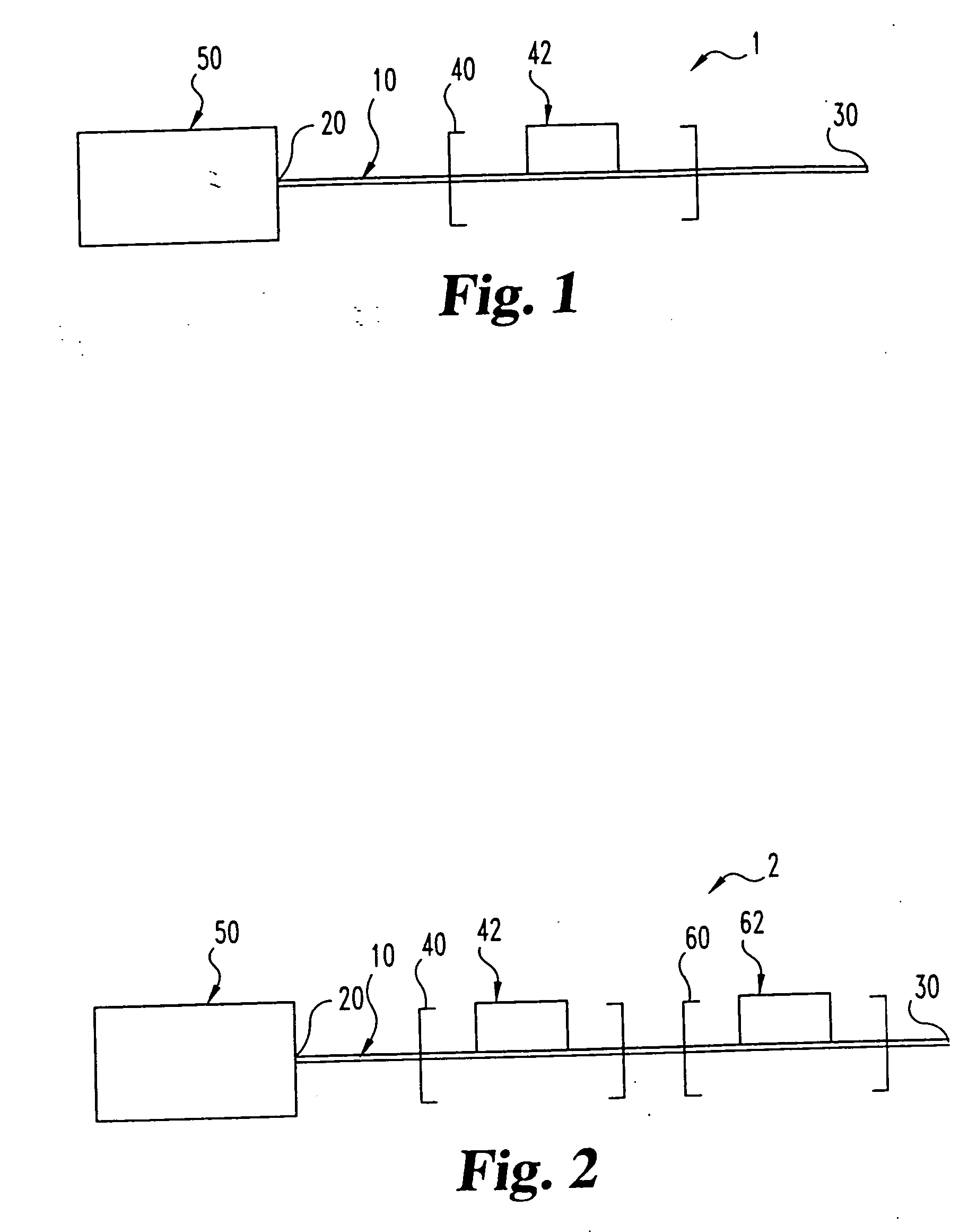
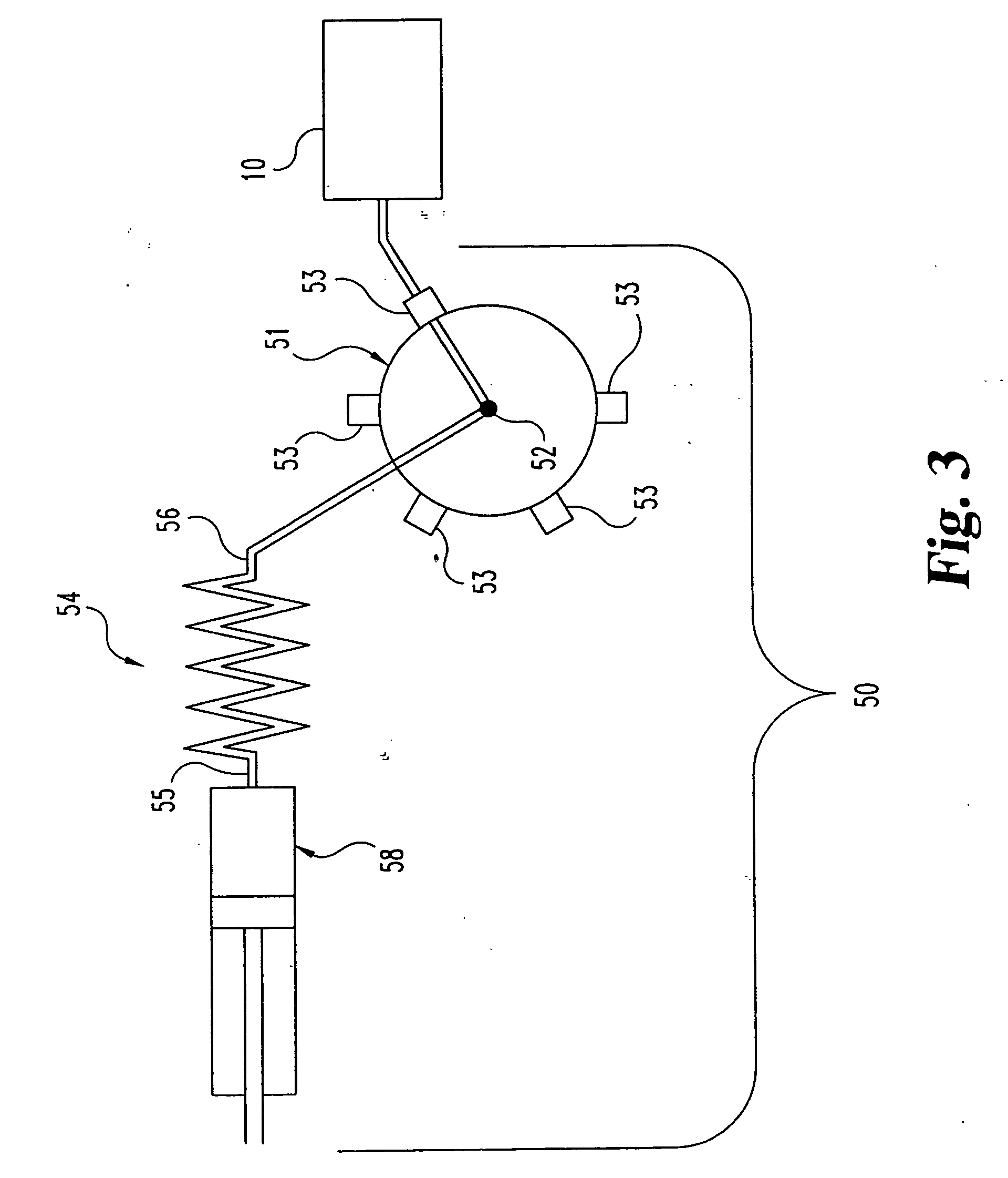
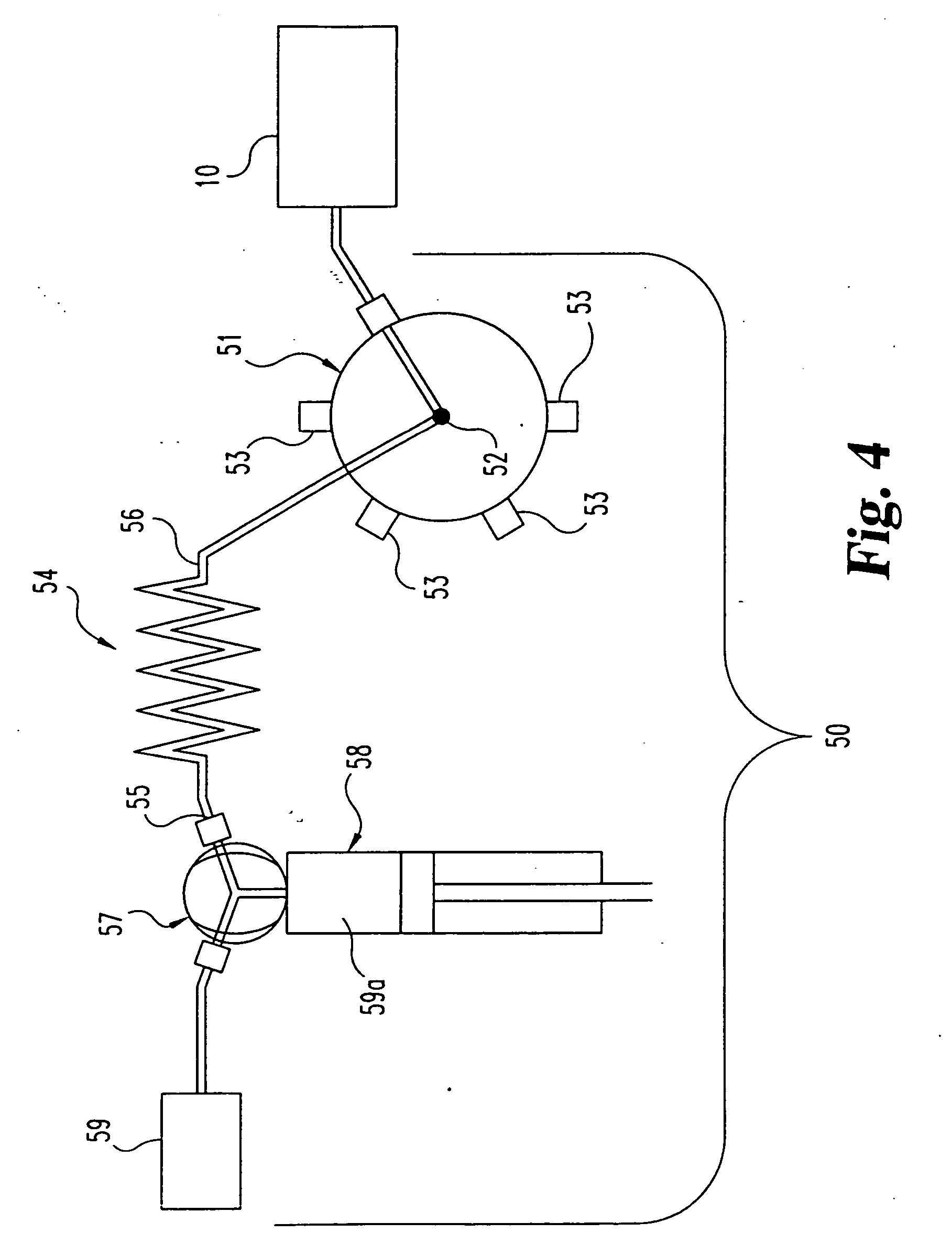
[0015] The present invention provides novel systems for conducting magnetic particle separations and resuspensions in one or more fluid media. In accordance with one aspect of the invention, magnetic particle capture and release are controlled by controlling the rate of fluid flow through a capture zone that passes through a fixed magnetic field. At low flow rates through the capture zone, the particles can be captured reproducibly and quantitatively. A high flow rate through the capture zone displaces the particles from the magnetic field.

Problems solved by technology

These steps are conducted in many such techniques by tedious manual pipetting and decanting procedures or by using automated robotic systems that are large and not field-portable.
One major challenge in the use of immobilized binding substances is the limited lifetime of a chemically selective surface, especially those that include biomolecules (often referred to as “biosensors”).
Therefore, it is not feasible to keep a biosensor surface immersed in aqueous solution continuously for long periods of use.
The use of whole cells in sensor systems is also challenging since cells require the correct mix of metabolites to remain viable, and solution composition and solution flow rate effect the growth rate of viable cells.
The specificity and therefore irreversible nature of many biospecific interactions also contributes to the limited lifetime of biosensing surfaces.
Harsh reagents may be used to remove bound antigens (and non-specifically bound molecules); however, this decreases the subsequent binding activity of the antibody itself so that the regenerated sensing surface is not as effective as the fresh sensing surface, negatively impacting assay accuracy and reliability.
In addition, the lifetime of a biosensor is often also limited due to “fouling” of the sensor surface caused by the non-specific binding of materials in a sample matrix onto the biosensor surface.
These problems have resulted in increased use of renewable surfaces for biosensing in which the chemically selective chemistry is on the surface of small particles.

Method used


Image

  • Flow-controlled magnetic particle manipulation
  • Flow-controlled magnetic particle manipulation
  • Flow-controlled magnetic particle manipulation

Examples


example one

Sequential Injection Analysis of TNT in Water Using an Enzyme-Linked Immunosorbent Assay

[0087] An experiment was conducted to demonstrate capture and resuspension of magnetic particles in an inventive system as follows:

[0088] Chemicals: TNT RaPID Assay™ kits provided the ELISA reagents (Strategic Diagnostics, Newark, Del.). The reagents used were a TNT-horseradish peroxidase (TNT-HRP) conjugate, a color development solution (3,3′5,5′-tetramethylbenzidine and H2O2), and the suspension of irregular 0.5 μm diameter magnetic particles with immobilized anti-TNT antibody. The color development reagent solution contained the chromogenic substrate 3,3′,5,5′-tetramethylbenzidine (TMB) and H2O2. Exact formulations are proprietary, but optimized reagent formulations have been published for similar atrazine ELISAs using HRP-atrazine conjugate and TMB. C. S. Hottenstein, F. M. Rubio, D. P. Herzog, J. R. Fleeker and T. S. Lawruk, “Determination of trace atrazine levels in water by a sensitive m...

example two

Cleaning of Apparatus Between Assays

[0118] Carryover cleaning. To eliminate carryover from one sample the next, the system was cleaned with acetone using the steps described in Table 2. This wash procedure takes two minutes.

TABLE 2Sequential Injection Procedure for Cleaning Between Runs.FlowVolume,Rate,Procedural StepSolutionPortμlμl / s1Place acetonevial at mixinlet2Initialize mixAcetonemixinlet3AspirateAcetonemix90504Fill the cellAcetonecell−852005AspirateAcetonemix450 −inletVol506Remove acetonevial7Empty the inletAcetonemixinletVol50line8Soak for 60seconds9DiscardAcetonecell−45050through cell10Rinse the mixWashmix−inletVol50inlet11Empty the inletWashmixinletVol50line12Rinse the cellWashcell−inletVol −15020013Restore the mixinlet

[0119] The automated acetone cleaning procedure outlined in Table 2 was effective at removing TNT carryover from the semi-automated method up to and including the maximum tested concentration of 5000 ng / ml TNT. The carryover error without cleaning was cha...

example three

Methodology, Fully Automated Procedure

[0120] The automated method was the same as the semi-automated method except that mixing of sample and reagents was automated by pulling sample, particle suspension, and TNT-HRP solution as stacked zones into the holding coil. Zone volumes for sample, particles, and TNT-HRP were 10 μl, 15 μl, and 15 μl, respectively, and the zone stacking was repeated 10 times to yield the total solution volumes of 100, 150, and 150 μl. An important difference between the semi-automated and automated procedure is that in the automated procedure, free sample TNT is pulled into the flow system and can adsorb to tubing or valve surfaces. In the semi-automated procedure, the TNT has the opportunity to bind to the magnetic particles before being handled in the flow system.

[0121] The 3-part mixture was injected to the capture cell immediately after zone stacking. Therefore, the competitive assay incubation time of the automated method was defined by the time require...


PUM

PropertyMeasurementUnit
volumeaaaaaaaaaa
diameteraaaaaaaaaa
sizeaaaaaaaaaa

Abstract

Inventive methods and apparatus are useful for collecting magnetic materials in one or more magnetic fields and resuspending the particles into a dispersion medium, and optionally repeating collection/resuspension one or more times in the same or a different medium, by controlling the direction and rate of fluid flow through a fluid flow path. The methods provide for contacting derivatized particles with test samples and reagents, removal of excess reagent, washing of magnetic material, and resuspension for analysis, among other uses. The methods are applicable to a wide variety of chemical and biological materials that are susceptible to magnetic labeling, including, for example, cells, viruses, oligonucleotides, proteins, hormones, receptor-ligand complexes, environmental contaminants and the like.

Description

RELATED APPLICATIONS [0001] This application is a divisional of U.S. patent application Ser. No. 09 / 944,816 filed Aug. 31, 2001, now abandoned.GOVERNMENT RIGHTS STATEMENT [0002] This invention was made with Government support under Contract Number DE-AC0676RLO1830 awarded by the U.S. Department of Energy. The Government has certain rights in the invention.BACKGROUND OF THE INVENTION [0003] The present invention relates to systems for the magnetic collection of magnetically-responsive particles (referred to herein as “magnetic particles”), and the subsequent controlled dispersion of the particles. In particular, the invention relates to the detection, isolation, separation and / or manipulation of target substances, such as for example, chemicals and / or biological substances such as biochemicals, cells, cell components, bacteria, viruses, toxins, nucleic acids, hormones, proteins, receptor-ligand complexes, other complex molecules, or combinations thereof, by selective interaction ther...

Claims


Application Information

Patent Timeline
Patent Type & Authority Applications(United States)
IPC IPC(8): G01N33/53G01N33/551B01L3/00B03C1/00C12M1/34C12M1/42C12Q1/25G01N33/543G01N35/00G01N35/08
CPCB01J2219/005B01J2219/00722B01J2219/00725B01J2219/00743B01L3/5027B03C1/00Y10T436/111666G01N33/54333G01N35/08G01N2035/00237G01N35/0098Y10T436/11Y10T436/112499G01N27/745
Inventor GRATE, JAY W.BRUCKNER-LEA, CYNTHIA J.HOLMAN, DAVID A.
Owner BATTELLE MEMORIAL INST
Why Eureka
Try Eureka