Exhaust gas purifying apparatus

a technology of exhaust gas and purification apparatus, which is applied in the direction of lighting and heating apparatus, machine/engine, separation process, etc., can solve the problems of insufficient supply of insufficient and insufficient supply of ammonia to the nox reducing catalytic converter, etc., to enhance the efficiency of hydrolysis of urea aqueous solution and short time

Inactive Publication Date: 2007-05-17
NISSAN DIESEL MOTOR CO
View PDF6 Cites 35 Cited by
  • Summary
  • Abstract
  • Description
  • Claims
  • Application Information

AI Technical Summary

Benefits of technology

[0011] With the exhaust gas purifying apparatus according to the invention, the internal tubular member is heated from outside and inside by the exhaust gas flowing through the exhaust pipe, and temperature of the internal tubular member rises to substantially the same temperature as that of the exhaust gas in an extremely short time. Therefore, temperature of the urea aqueous solution additively injected into the internal tubular member does not decrease even if the solution adheres to an inner wall of the internal tubular member to form liquid droplets, to thereby enhance efficiency of hydrolysis of the urea aqueous solution. Since the efficiency of the hydrolysis of the urea aqueous s

Problems solved by technology

Because an outer wall of the exhaust pipe is in contact with the atmospheric air and is at a low temperature as compared with the exhaust gas, the liquid droplets formed on the inner wall by the urea aqueous solution are not sufficiently heated and become difficult to hydrolyze to the ammonia.
For this reason, there is a possibility that the ammonia to be supplied to the NOx r

Method used


Image

  • Exhaust gas purifying apparatus
  • Exhaust gas purifying apparatus
  • Exhaust gas purifying apparatus

Examples


first embodiment

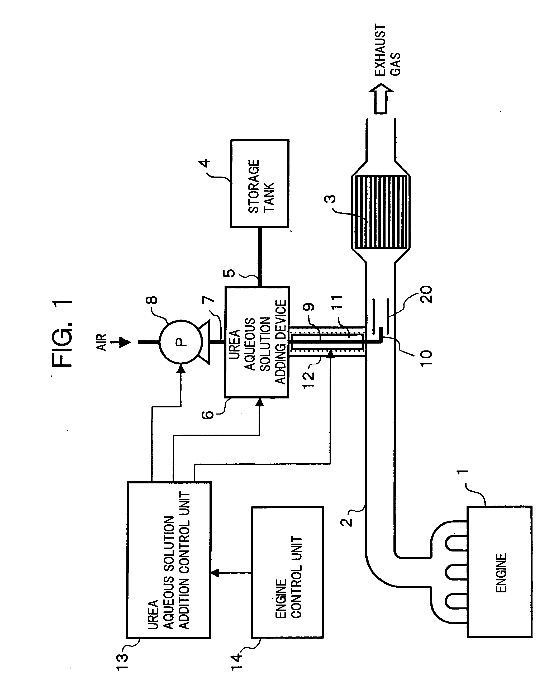
[0019]FIG. 1 shows an exhaust gas purifying apparatus according to the invention.

[0020] In an exhaust pipe 2 forming an exhaust passage of an engine 1, a NOx reducing catalytic converter 3 for reducing and purifying NOx is disposed. The NOx reducing catalytic converter 3 is formed by supporting a zeolite active component, for example, on a monolith-type catalyst carrier made of ceramic cordierite or Fe—Cr—Al heat resisting steel and having a honeycomb-shaped cross section. The active component supported on the catalyst carrier is activated when ammonia as a reducing agent is supplied, and effectively converts NOx to harmless substances.

[0021] The exhaust gas purifying apparatus is provided with a storage tank 4 for storing a urea aqueous solution. The storage tank 4 is connected to a urea aqueous solution adding device 6 through piping 5. On the other hand, the urea aqueous solution adding device 6 is connected to a pump 8 through piping 7. The pump 8 pressurizes air and supplies t...

third embodiment

[0033]FIG. 4 shows the exhaust gas purifying apparatus according to the invention.

[0034] In the embodiment, in order to heat the urea aqueous solution stored in the storage tank 4 by a coolant of the engine 1, a configuration in which piping 22 for the coolant is made to pass through the storage tank 4 is employed. In this way, without using the electric heater, the urea aqueous solution stored in the storage tank 4 is heated and the temperature of the solution is increased by utilizing waste heat. Accordingly, it is possible to suppress an energy consumption required to increase the temperature of the urea aqueous solution. In the embodiment, the piping 22 corresponds to the heating device.

fourth embodiment

[0035]FIG. 5 shows the exhaust gas purifying apparatus according to the invention.

[0036] In the embodiment, in order to heat the urea aqueous solution to be supplied to the urea aqueous solution adding device 6, a configuration is employed in which an intermediate portion of the piping 5 connecting the storage tank 4 and the urea aqueous solution adding device 6 is wound around the exhaust pipe 2 positioned on the exhaust downstream side of the NOx reducing catalytic converter 3. In this way, without using the electric heater, the urea aqueous solution flowing through the piping 5 can receive heat from the exhaust gas flowing through the exhaust pipe 2 and the temperature of the solution is increased by utilizing wasted heat. Therefore, it is able to suppress the energy consumption required to increase the temperature of the urea aqueous solution. At this time, because the exhaust heat on the exhaust downstream side of the NOx reducing catalytic converter 3 is utilized, the temperat...


PUM

PropertyMeasurementUnit
Temperatureaaaaaaaaaa
Flow rateaaaaaaaaaa

Abstract

An exhaust pipe for an exhaust gas is provided, at its position on upstream side of nitrogen oxides (NOx) catalytic converter, with an internal tubular member disposed to have open opposite ends in a direction along exhaust gas flow while leaving a clearance between internal tubular member and exhaust pipe inner wall. A urea aqueous solution from the storage tank is additively injected by an injection nozzle in a direction of exhaust gas flow within internal tubular member capable of being heated by exhaust gas in exhaust pipe, to thereby shortly bring temperature of internal tubular member to become substantially equal to an exhaust gas temperature. Thus, temperature of urea aqueous solution additively injected into internal tubular member does not decrease when the solution adheres to an inner wall of that tubular member forming liquid droplets, thereby enhancing hydrolysis an inner wall of urea aqueous solution.

Description

[0001] This application is a continuation of PCT / JP2004 / 012747, filed on Sep. 2, 2004.BACKGROUND OF THE INVENTION [0002] 1. Field of the Invention [0003] The present invention relates generally to an apparatus for reducing and purifying nitrogen oxides (NOx) in an exhaust gas exhausted from diverse kinds of power generators such as, for example, a vehicle engine and so forth, and more particularly to a technology for enhancing efficiency of hydrolysis of a urea aqueous solution used as a reducing agent in the exhaust gas purifying apparatus in order for reducing and purifying NOx component in an exhaust gas exhausted from an engine. [0004] 2. Description of the Related Art [0005] Japanese Unexamined Patent Publication No. 2000-27627 (JP-A-2000-027627) discloses a conventional exhaust gas purifying apparatus for reducing and purifying NOx included in the exhaust gas exhausted from an engine. In this exhaust gas purifying apparatus, a NOx reducing catalytic converter is disposed in an...

Claims


Application Information

Patent Timeline
IPC IPC(8): B01D53/34
CPCF01N3/2066F01N5/02F01N2610/02F01N2610/10F01N2610/102Y02T10/16Y02T10/24Y02T10/12
Inventor HIRATA, KIMINOBU
Owner NISSAN DIESEL MOTOR CO
Why Eureka
Try Eureka