Sensor system for measuring an electric potential signal of an object

Active Publication Date: 2007-06-14
QUANTUM APPLIED SCI & RES
View PDF14 Cites 21 Cited by
  • Summary
  • Abstract
  • Description
  • Claims
  • Application Information

AI Technical Summary

Benefits of technology

[0015] The invention generally pertains to reducing artifact noise signals that are generally present when non-invasive capacitive type measurements are taken of a body. More specifically, the invention pertains to reducing the artifact signals measured by a capacitive sensor when the sensor is operated in a static electric field produced by an object of interest. According to a first preferred em

Problems solved by technology

While the system set forth in the '800 patent is effective, almost all capacitive measurements that occur in real world environments are degraded by artifact signals and noise caused by the presence of static electric fields.
An important limiting factor in capacitive measurements is the behavior of static electric potential in the region where sensors must be located to measure a signal of interest.
Such changes in the sensed potential can saturate the capacitive electrode causing large changes in the output signal produced by the sensor.
Such artifact signals can often be very similar in frequency to the signal of interest and thus are typically very difficult to filter.
In the case of a sensed bioelectric signal, certain artifact signals, such as common mode signals, can be particularly troublesome.
The opposite is also true and can lead to measuring equipment reading an irregular heartbeat or fibrillation when the heartbeat is actually normal.
However, no simple way of eliminating such signals is proposed.
Since, by its very nature, a non-invasive capacitive measurement system cannot make a resistive coupled electric

Method used


Image

  • Sensor system for measuring an electric potential signal of an object
  • Sensor system for measuring an electric potential signal of an object
  • Sensor system for measuring an electric potential signal of an object

Examples


Embodiment Construction

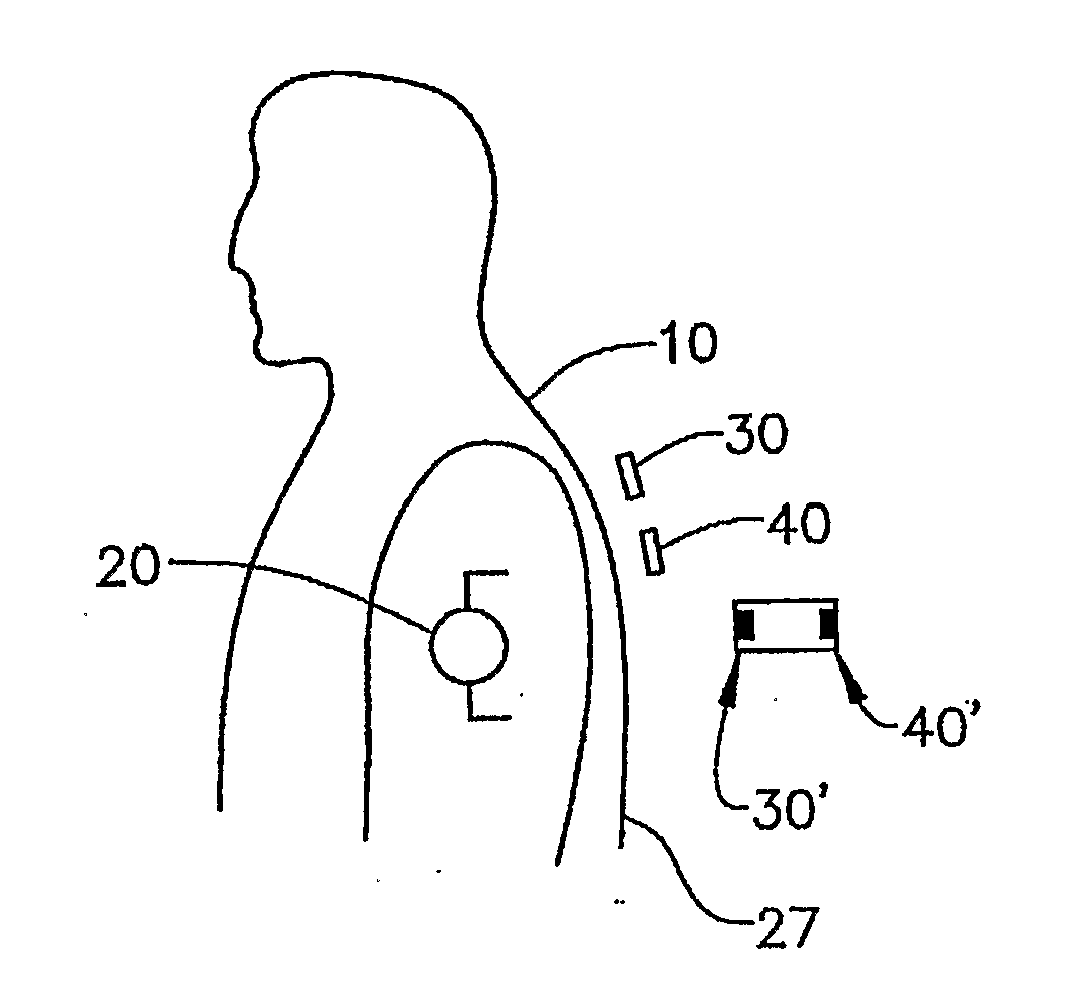
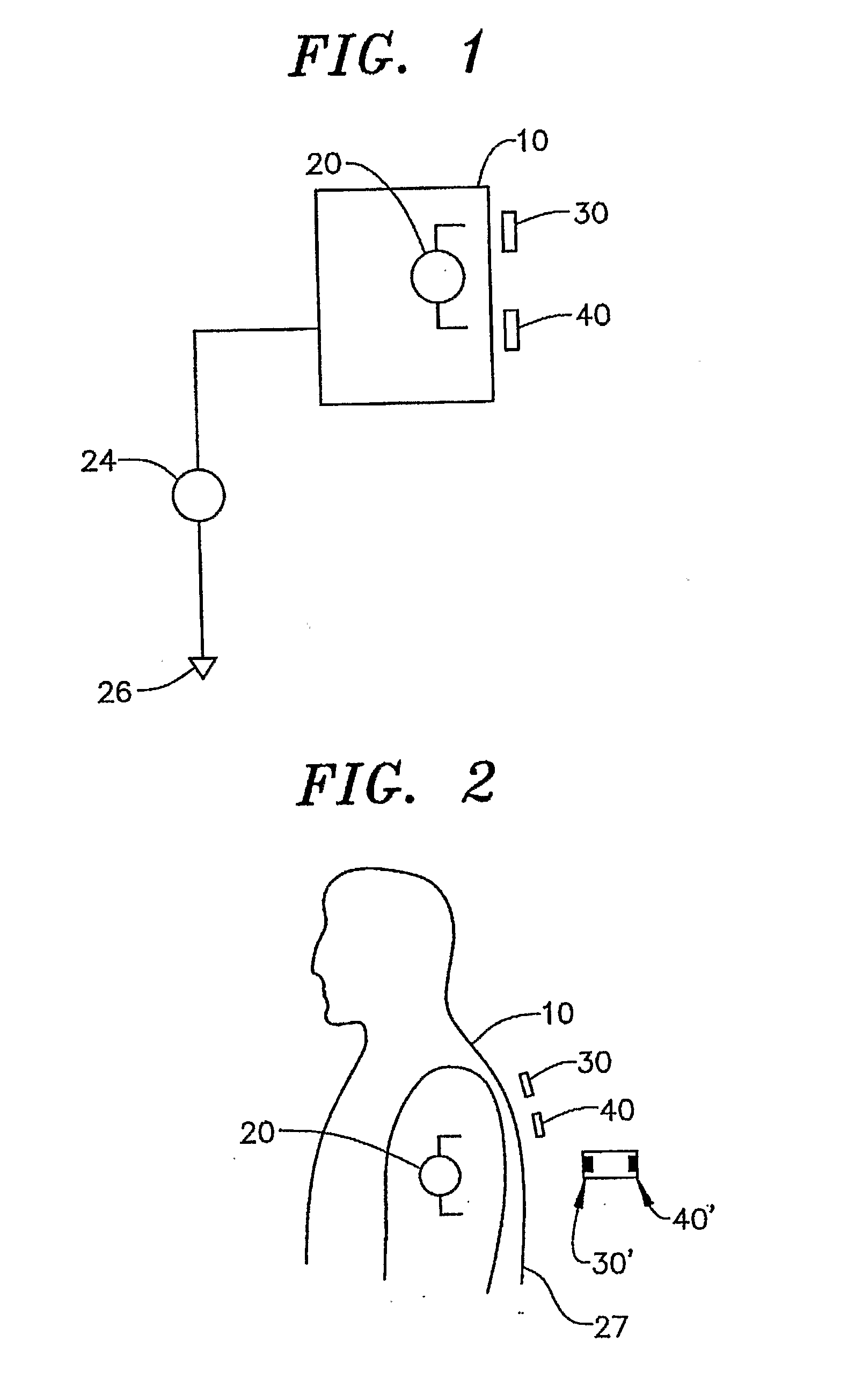
[0029] The overall system for measuring a signal can be generally discussed with reference to FIG. 1. An object or body 10 has a source 20 of alternating current type voltage located therein. This voltage source 20 produces a voltage signal of interest that is to be measured. Object 10 is large compared to the spatial variation of the signal of interest produced by voltage source 20. Object 10 is charged to a static potential 24 relative to a distant point which we will define as a ground 26 having a voltage or potential of zero. The conductivity of object 10 is such that the static potential 24 at its surface 27 is substantially uniform compared to the spatial variation of the signal of interest. Further, object 10 maintains this spatial uniformity over the timescales of interest even when the static potential 24 suddenly changes. An example of such an object would be an aircraft, a human body, or a partly conducting shield placed over a sensor to protect it from the environment. S...


PUM


Abstract

The invention generally pertains to reducing artifact noise signals present when non-invasive capacitive-type signal measurements are taken of static electric fields produced by an object (10) of interest. According to a first preferred embodiment of the invention, a given static artifact signal is reduced by minimizing the potential difference between a ground point (G1) of sensor circuitry and the potential of the object (10). According to a second preferred embodiment of the invention, the change in signal due to motion of the sensor (30, 40; 30′, 40′; 230; 330; 430; 530; 630) in the field produced by the object (10) is minimized by reducing the impact of changes in coupling to the signal source.

Description

CROSS-REFERENCE TO RELATED APPLICATION [0001] The present application claims the benefit of U.S. Provisional Patent Application Ser. No. 60 / 584,146 entitled “Method to Reduce the Effect of Static Potentials in Capacitive Measurements” filed Jul. 1, 2004.STATEMENT OF GOVERNMENT INTEREST [0002] The United States Government retains a royalty fee, fully paid up, non-exclusive license to make, use, have made, or have the invention used for governmental purposes. BACKGROUND OF THE INVENTION [0003] 1. Field of the Invention [0004] The present invention pertains to measuring an electric potential signal generated by an object and, more particularly, to reducing the effect of artifact signals or signals caused by a change in static potential on measurement of an electric potential signal of interest. [0005] 2. Discussion of the Prior Art [0006] Capacitive electrodes that sense the electrical potential produced in the space surrounding a voltage source enable many important new measurement mo...

Claims


Application Information

Patent Timeline
IPC IPC(8): H03F3/45A61B5/04
CPCA61B5/0408A61B5/04284A61B5/0478G01R29/12A61B5/25A61B5/302A61B5/291
Inventor FRIDMAN, IGORHERVIEUX, PAULKUNSTMANAS, LINASMATTHEWS, ROBERT
Owner QUANTUM APPLIED SCI & RES
Why Eureka
Try Eureka