Surface engineering of bipolar plate materials for better water management

a technology of bipolar plates and materials, applied in the field of bipolar plates for fuel cells, can solve the problems of reducing the overall efficiency of the fuel cell, reducing the electrical performance, and water accumulating in the interior, and achieve the effect of less hydrophilic and increased hydrophilic nature of the coating

Inactive Publication Date: 2007-06-21
GM GLOBAL TECH OPERATIONS LLC
View PDF9 Cites 20 Cited by
  • Summary
  • Abstract
  • Description
  • Claims
  • Application Information

AI Technical Summary

Benefits of technology

[0013] In accordance with the teachings of the present invention, a flow field plate or bipolar plate for a fuel cell is disclosed, where a surface of the flow field plate is textured or roughened to change the surface morphology of the plate. A conductive coating is deposited on the roughened surface where the roughness of the surface of the plate increases the hydrophilic nature of the coating. Therefore, if the coating is naturally hydrophobic (water contact angle of 90°), the surface roughness makes the coating hydrophilic to wick water away. If the coating is a conductive hydrophilic coating (water contact angle of 40°), then the surface roughness makes the coating super-hydrophilic (water contact angle of 0°), and may counter the effects of surface contamination that would act to make the hydrophilic coating less hydrophilic.

Problems solved by technology

However, the oxide layer is not conductive, and thus increases the internal resistance of the fuel cell, reducing its electrical performance.
At low cell power demands, typically below 0.2 A / cm2, the water may accumulate within the flow channels because the flow rate of the reactant gas is too low to force the water out of the channels.
Those areas of the membrane that do not receive reactant gas as a result of the channel being blocked will not generate electricity, thus resulting in a non-homogenous current distribution and reducing the overall efficiency of the fuel cell.
As more and more flow channels are blocked by water, the electricity produced by the fuel cell decreases, where a cell voltage potential less than 200 mV is considered a cell failure.
However, on the cathode side, this increases the parasitic power applied to the air compressor, thereby reducing overall system efficiency.
Moreover, there are many reasons not to use the hydrogen fuel as a purge gas, including reduced economy, reduced system efficiency and increased system complexity for treating elevated concentrations of hydrogen in the exhaust gas stream.
A dry inlet gas has a drying effect on the membrane that could increase the cell's ionic resistance, and limit the membrane's long-term durability.
For the roughly rectangular channels used in current fuel cell stack designs with composite bipolar plates, this sets an approximate upper limit on the contact angle needed to realize the beneficial effects of hydrophilic plate surfaces on channel water transport and low load stability.

Method used


Image

  • Surface engineering of bipolar plate materials for better water management
  • Surface engineering of bipolar plate materials for better water management
  • Surface engineering of bipolar plate materials for better water management

Examples


Embodiment Construction

[0020] The following discussion of the embodiments of the invention directed to a bipolar plate for a fuel cell that includes a roughened surface to make a coating deposited thereon more hydrophilic is merely exemplary in nature, and is in no way intended to limit the invention or its applications or uses.

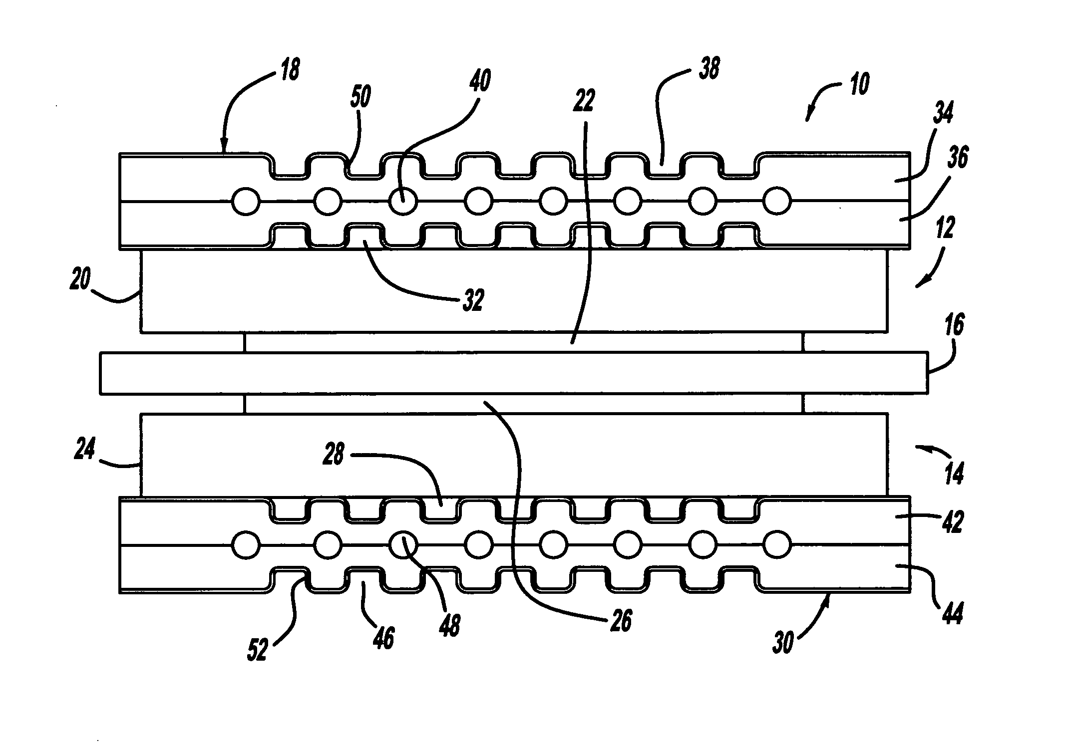
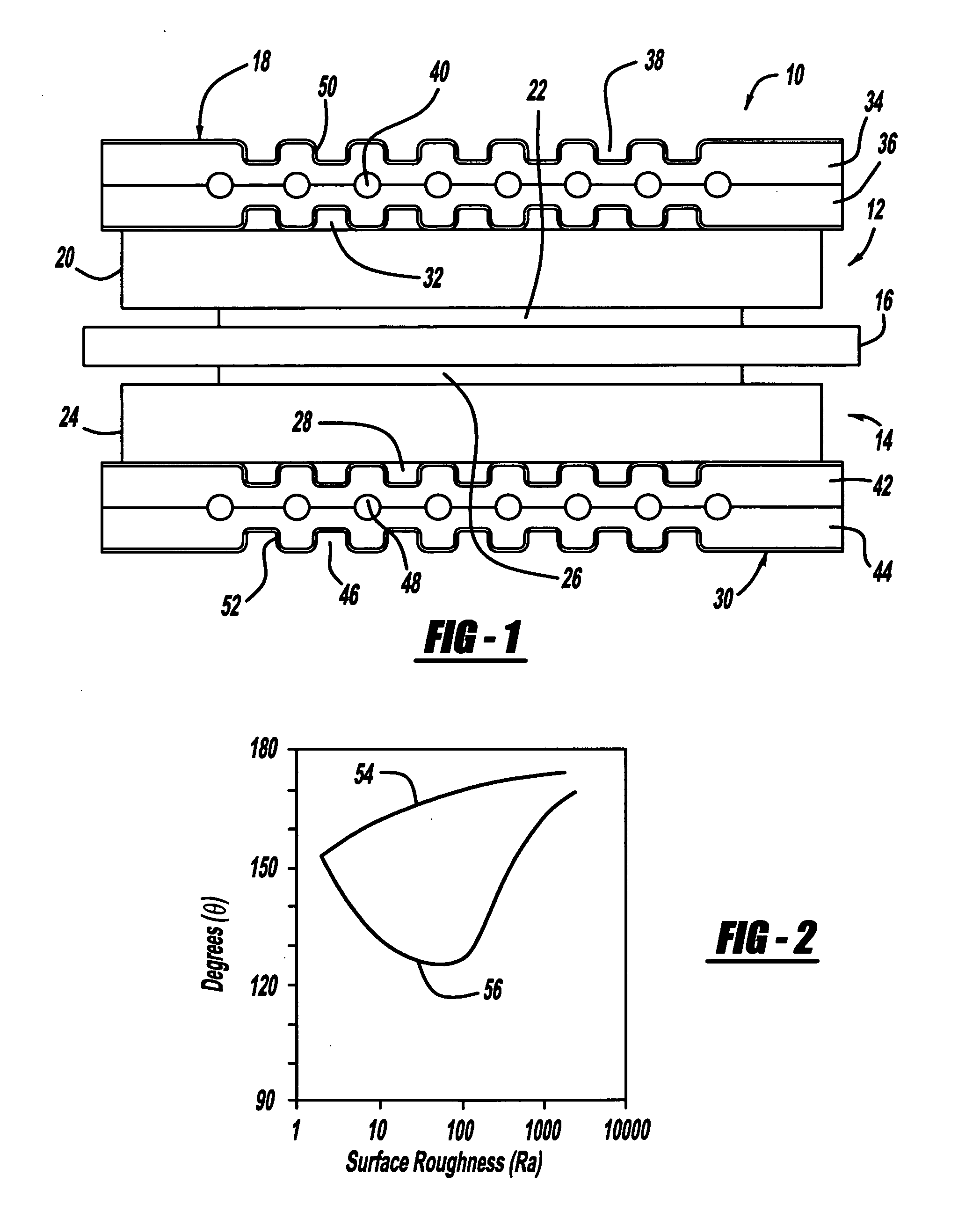
[0021]FIG. 1 is a cross-sectional view of a fuel cell 10 that is part of a fuel stack of the type discussed above. The fuel cell 10 includes a cathode side 12 and an anode side 14 separated by a perfluorosulfonic acid membrane 16. A cathode side diffusion media layer 20 is provided on the cathode side 12, and a cathode side catalyst layer 22 is provided between the membrane 16 and the diffusion media layer 20. Likewise, an anode side diffusion media layer 24 is provided on the anode side 14, and an anode side catalyst layer 26 is provided between the membrane 16 and the diffusion media layer 24. The catalyst layers 22 and 26 and the membrane 16 define an MEA. The diffusion media l...


PUM

PropertyMeasurementUnit
thicknessaaaaaaaaaa
cell voltage potentialaaaaaaaaaa
static contact angleaaaaaaaaaa

Abstract

A flow field plate or bipolar plate for a fuel cell, where a surface of the flow field plate is textured or roughened to change the surface morphology of the plate. A conductive coating is deposited on the roughened surface where the roughness of the surface of the plate increases the hydrophilic nature of the coating. Therefore, if the coating is naturally hydrophobic, the surface roughness makes the coating hydrophilic to wick water away. If the coating is a conductive hydrophilic coating, then the surface roughness makes the coating super-hydrophilic, and may counter the effects of surface contamination that would act to make the hydrophilic coating less hydrophilic.

Description

BACKGROUND OF THE INVENTION [0001] 1. Field of the Invention [0002] This invention relates generally to bipolar plates for fuel cells and, more particularly, to a bipolar plate for a fuel cell that includes a hydrophobic or hydrophilic coating deposited on a roughened surface of the plate. [0003] 2. Discussion of the Related Art [0004] Hydrogen is a very attractive fuel because it is clean and can be used to efficiently produce electricity in a fuel cell. A hydrogen fuel cell is an electrochemical device that includes an anode and a cathode with an electrolyte therebetween. The anode receives hydrogen gas and the cathode receives oxygen or air. The hydrogen gas is dissociated in the anode to generate free protons and electrons. The protons pass through the electrolyte to the cathode. The protons react with the oxygen and the electrons in the cathode to generate water. The electrons from the anode cannot pass through the electrolyte, and thus are directed through a load to perform wo...

Claims


Application Information

Patent Timeline
Patent Type & Authority Applications(United States)
IPC IPC(8): H01M8/02B05D5/12
CPCH01M8/0204H01M8/0206H01M8/021H01M8/0213H01M8/0221H01M8/0226H01M8/0228H01M8/04291H01M2008/1095H01M2250/20Y02T90/32Y02E60/50Y02T90/40
Inventor VYAS, GAYATRIELHAMID, MAHMOUD H. ABDMIKHAIL, YOUSSEF M.TRABOLD, THOMAS A.
Owner GM GLOBAL TECH OPERATIONS LLC
Why Eureka
Try Eureka