Control apparatus for electric vehicles

a technology for controlling apparatus and electric vehicles, applied in the direction of electric devices, process and machine control, instruments, etc., can solve the problem that the system voltage cannot be stabilized sufficiently, and achieve the effect of suppressing system voltage variations

Active Publication Date: 2007-06-28
DENSO CORP
View PDF23 Cites 32 Cited by
  • Summary
  • Abstract
  • Description
  • Claims
  • Application Information

AI Technical Summary

Benefits of technology

[0017] For this reason, the selector selects one or more the MG units and/or the voltage converter in accordance with the operating state of the electric vehicle, whereas the system voltage control unit executes the system voltage stabilization control to suppress variations in the system voltage by controlling powers handled by the selected MG units and/or the voltage converter. Thus, when the state of driving the MG units (or the state of power generation in the MG units) and/or the state of driving the voltage converter change due to a variation of the operating state of the electric vehicle so that the upper limit of the input power operation quantity of each MG unit also changes, the selector selects the above MG units and/or ...

Problems solved by technology

In such a condition, the target input power operation quantity required for stabilization of the system volta...

Method used


Image

  • Control apparatus for electric vehicles
  • Control apparatus for electric vehicles
  • Control apparatus for electric vehicles

Examples


first embodiment

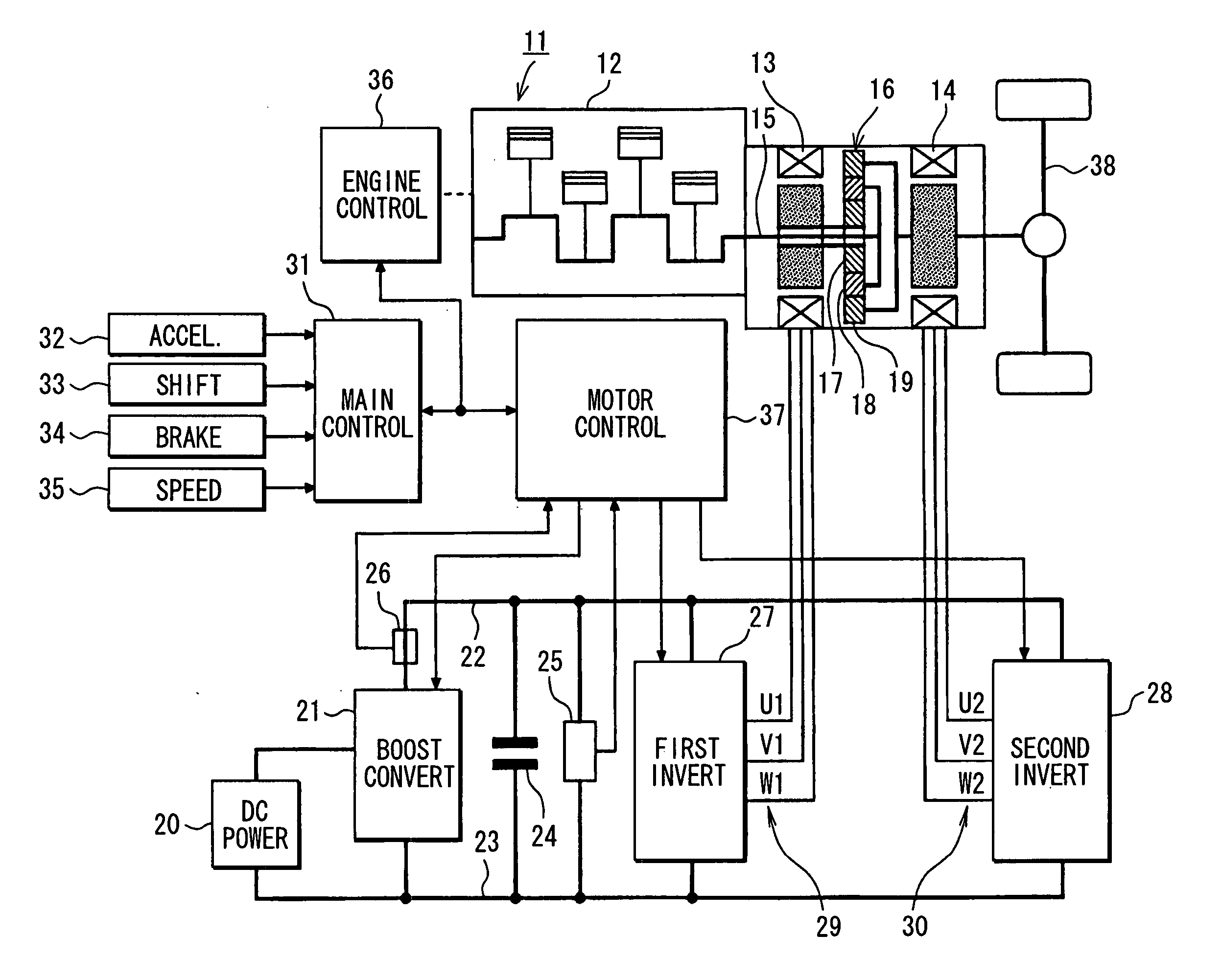
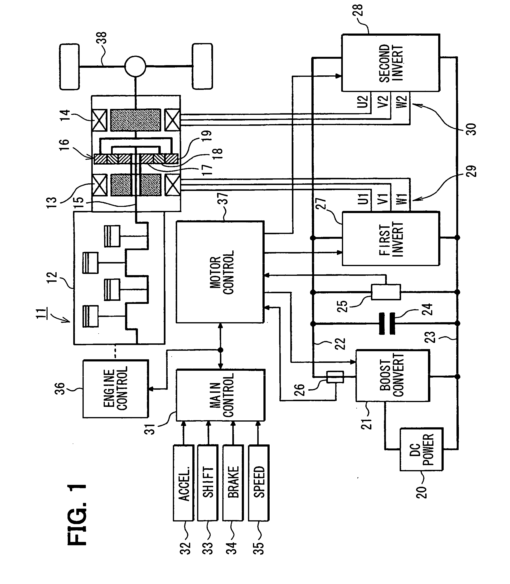
[0034] Referring first to FIG. 1, an electric vehicle 11 has an internal combustion engine 12 in addition to a first AC motor 13 and a second AC motor 14. Thus, the electric vehicle 11 is an engine / motor hybrid vehicle. The engine 12 and the second AC motor 14 are employed as a drive power source for driving the electric vehicle 11. Power generated by a crankshaft 15 of the engine 12 is divided into two paths by a planetary gear set 16. The planetary gear set 16 includes a sun gear 17, a planetary gear 18 and a ring gear 19. The sun gear 17 rotates at the center. The planetary gear 18 rotates along a circumference external to the sun gear 17 while revolving around the center of its own. The ring gear 19 rotates along a circumference external to the planetary gear 18. The planetary gear 18 is linked to the crankshaft 15 of the engine 12 through a carrier not shown in the figure. On the other hand, the ring gear 19 is linked to a rotation shaft of the second AC motor 14. The sun gear ...

second embodiment

[0096] In the first embodiment, the first AC motor 13 and the second AC motor 14 are controlled by the sinusoidal PWM control method. In a second embodiment shown in FIG. 7, on the other hand, the first AC motor 13 is controlled by the sinusoidal PWM control method but the second AC motor 14 is controlled by a rectangular waveform control method.

[0097] In execution of torque control on the second AC motor 14, the motor control unit 37 generates three-phase voltage command signals UU2, UV2 and UW2 by the rectangular waveform control method on the basis of the torque command value T2* output by the main control unit 31, the U-phase current iU2 and W-phase current iW2 of the second AC motor 14 as well as the rotor rotational position θ2 of the second AC motor 14. The rectangular waveform control method adopted for the second AC motor 14 is a method of changing electrical conduction of the AC motor 14 every predetermined value of an electrical angle of the AC motor 14.

[0098] In contro...

third embodiment

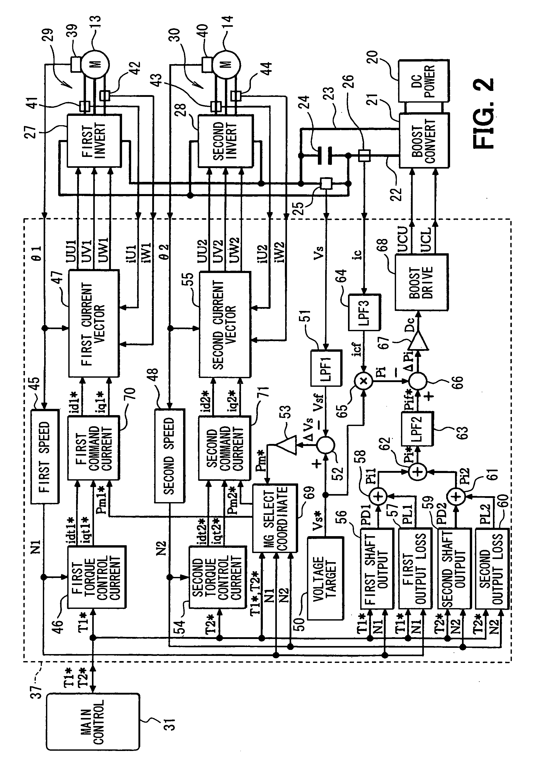
[0111] In a third embodiment shown in FIG. 10, the motor control apparatus 37 executes conversion power control of controlling a conduction duty ratio Dc of a switching device (not shown) as a device in the voltage boosting converter 21 so as to reduce the difference ΔPi between a command value Pif* of a power, which is output by the voltage boosting converter 21 as a conversion power, and a detected value Pi of the conversion power.

[0112] A total power Pi* is supplied to the second low pass filter 63 serving as the second low frequency component passing means for carrying out the low pass filtering process to pass only components included in the total power Pi* as components each having a low frequency. A post-filtering total power Pif* is obtained as a result of the low pass filtering process. An adder 87 at a stage following the second low pass filter 63 adds a target output power operation quantity Pmc* to the post-filtering total power Pif* to result in the final command value...


PUM


Abstract

In an electric vehicle having a plurality of MG units each including an AC motor and an inverter, a control apparatus executes system voltage stabilization control to suppress variations in a system voltage by adjusting an input power of a first MG unit or a second MG unit so as to reduce the difference between a target value and detected value of the system voltage. In execution of this control, either one or both of the MG units is selected by a selector by using information on the first MG unit and the second MG unit. The system voltage stabilization control is executed on the selected MG unit. Alternatively, the control apparatus may execute the system voltage stabilization control by selecting a voltage boosting converter.

Description

CROSS REFERENCE TO RELATED APPLICATION [0001] This application is based on and incorporates herein by reference Japanese Patent Applications No. 2005-372966 filed on Dec. 26, 2005, No. 2006-29810 filed on Feb. 7, 2006, No. 2006-308135 filed on November 14 and No. 2006-309072 filed on November 15. [0002] This application is related to five US patent applications (IPICS 99951-US, 100145-US, 100223-US, 100725-US, 101862-US and 103382-US) claiming priorities to the following Japanese Patent Applications, respectively: No. 2005-343750 filed on Nov. 29, 2005; No. 2005-353075 filed on Dec. 7, 2005; No. 2005-353076 filed on Dec. 7, 2005; No. 2005-371264 filed on Dec. 26, 2005; No. 2006-40272 filed on Feb. 17, 2006; and No. 2006-89713 filed on Mar. 29, 2006. FIELD OF THE INVENTION [0003] The present invention relates to a control apparatus for an electric vehicle including a system for converting a voltage generated by a DC power supply into a system voltage by using a voltage converte...

Claims


Application Information

Patent Timeline
IPC IPC(8): H02P7/00B60L50/10B60L50/15B60L50/16
CPCB60L3/0023B60K6/445B60L15/025B60L15/08B60L2240/42B60L2240/526B60W2510/085B60W2520/10B60W20/10H02P6/04B60L50/10B60L50/15B60L50/16Y02T10/64Y02T10/62Y02T10/70Y02T10/7072
Inventor EGAMI, TSUNEYUKIKAWAKAMI, KEIICHIOGAWA, TAKASHI
Owner DENSO CORP
Why Eureka
Try Eureka