Wire grid polarizer and method for producing same
a polarizer and wire grid technology, applied in the direction of polarising elements, instruments, optical elements, etc., can solve the problems of low light transmittance and quenching ratio, increased cost, and difficulty in producing polarizers using polar cores, etc., to achieve high quenching ratio, high transmittance, and high degree of polarization
- Summary
- Abstract
- Description
- Claims
- Application Information
AI Technical Summary
Benefits of technology
Problems solved by technology
Method used
Image
Examples
first preferred embodiment
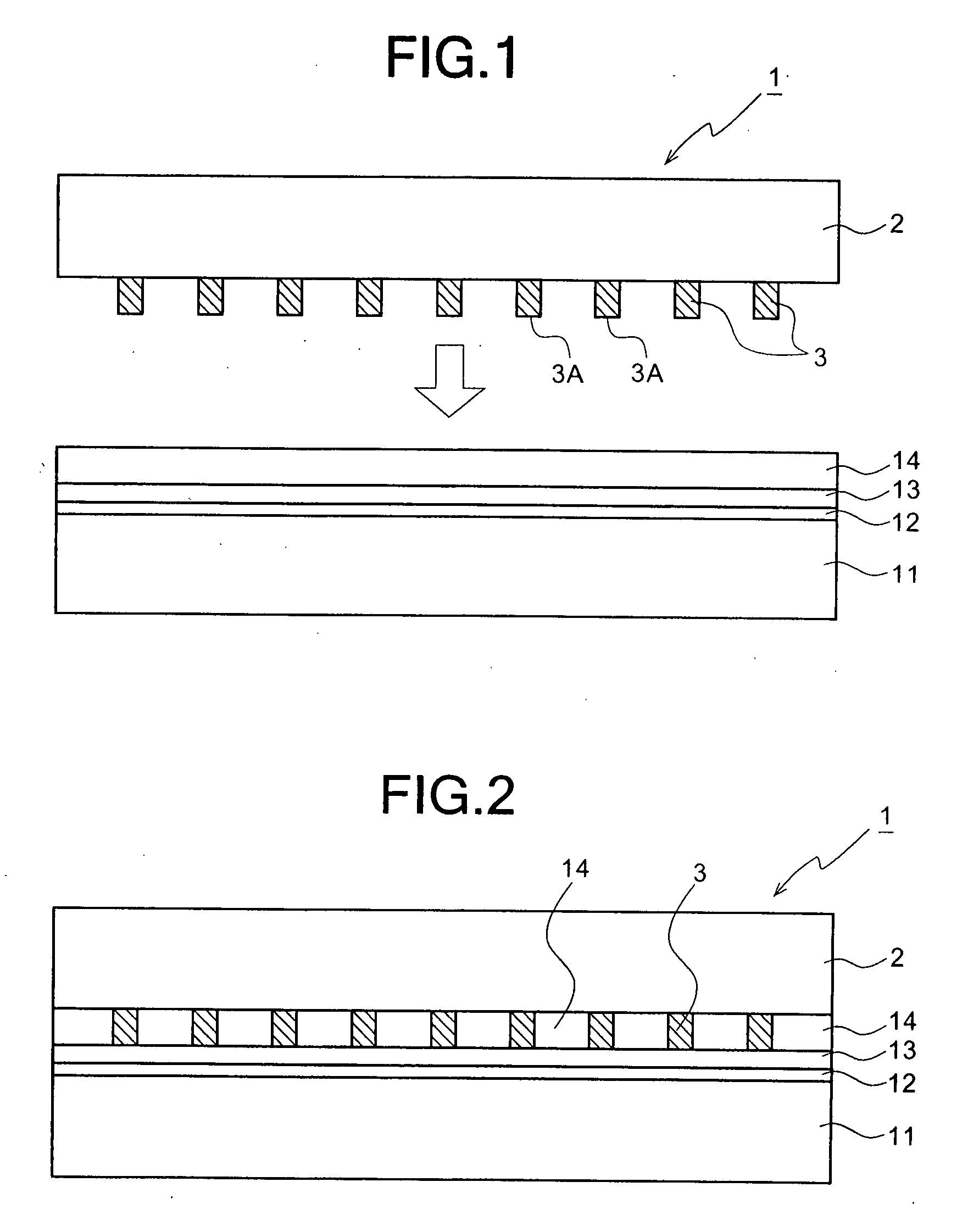
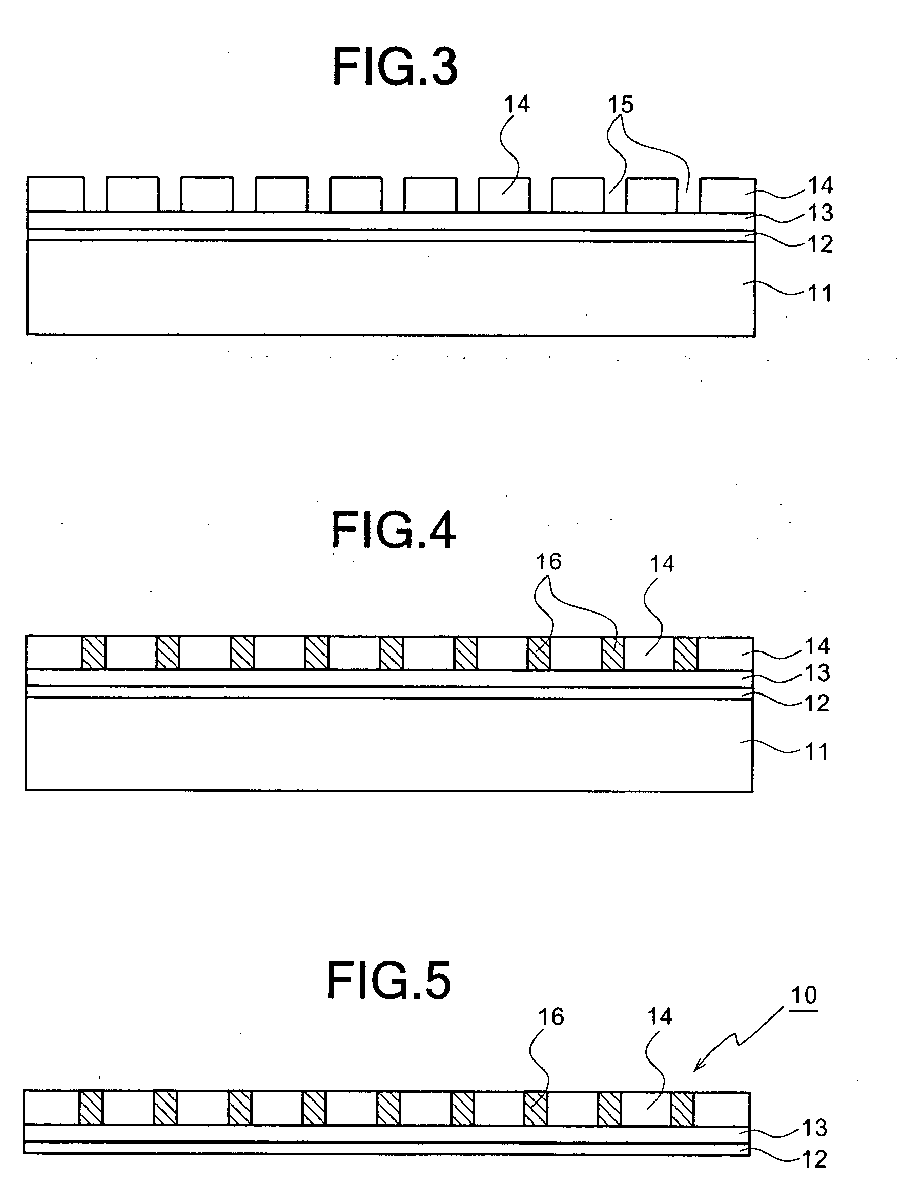
[0067] Referring now to the accompanying drawing, particularly to FIGS. 1 through 5, the first preferred embodiment of a wire grid polarizer and a method for producing the same according to the present invention will be described below.
[0068] First, as shown in FIG. 1, a die 1 for carrying out the nano-imprint lithography is prepared. The die 1 has a plurality of groove forming protrusions 3, which are formed on one side of a die substrate 2 of silicon or quarts by working a metal thin film, as an inverted pattern of metal fine wires (a wire grid) to be worked. That is, the width of each of the groove forming protrusions 3 of the metal thin film of the die 1, and the distance between adjacent two of the groove forming protrusions 3 thereof are set to be the same as the preset width and distance with respect to metal thin wires 16 of a wire grid polarizer 10 which will be described later. Furthermore, in the die 1, the period of the groove forming protrusions 3 (the distance between...
second preferred embodiment
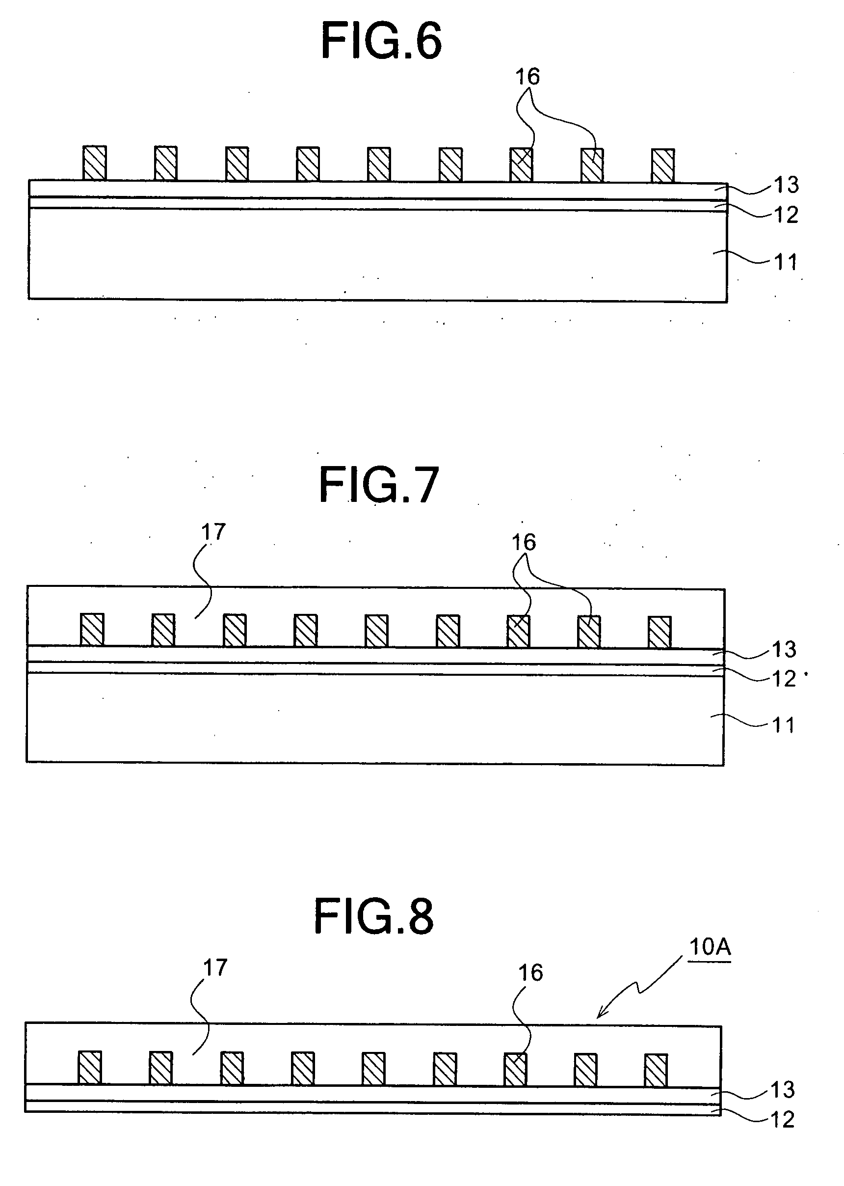
[0085] Referring to FIGS. 9 and 10, the second preferred embodiment of the present invention will be described below. In this preferred embodiment, the same steps as those shown in FIGS. 1 through 4 are carried out. After the metal fine wires 16 are caused to grow in the metal fine wire forming grooves 15 of the hydrophobic thin film 14 as shown in FIG. 4, the hydrophobic thin film 14 and the metal fine wires 16 are coated with a transparent protective film 18 as shown in FIG. 8. For example, in the process for forming the protective film 18, after the glass substrate 11 is set on the turntable of a spin coater, the glass substrate 11 may be spin-coated with the liquid material of the protective film 18 to be baked. Furthermore, the liquid material of the protective film 18 may be a resist or PMMA dissolved in an organic solvent, similar to the hydrophobic thin film 14.
[0086] Thereafter, as shown in FIG. 10, the glass substrate 11 is peeled off from the fluoridated polyimide thin f...
third preferred embodiment
[0087] Referring to FIGS. 11 through 13, the third preferred embodiment of the present invention will be described below. In this preferred embodiment, the glass substrate 11 is used as part of a polarizer without being peeled off.
[0088] First, in the third preferred embodiment, a hydrophilic thin film 13 being a transparent hydrophilic polymer thin film is formed on the glass substrate 11. Specifically, after a thin film, such as a resist, is spin-coated to be baked, the backed film is irradiated with ultraviolet or processed with plasma of argon (Ar) or the like, so that the hydrophilic thin film 13 can be formed. As an example of such a resist, Glassia (trade name), which is commercially available from Nippon Paint Co., Ltd., may be used.
[0089] Then, a hydrophobic thin film 14 is applied on the hydrophilic thin film 13 to be baked. Then, after a nano-imprint lithography process is carried out similar to the above described first preferred embodiment, metal fine wires 16 are sel...
PUM
| Property | Measurement | Unit |
|---|---|---|
| wavelength | aaaaa | aaaaa |
| wavelength | aaaaa | aaaaa |
| wavelength | aaaaa | aaaaa |
Abstract
Description
Claims
Application Information
 - R&D
- Intellectual Property
- Life Sciences
- Materials
- Tech Scout
- Unparalleled Data Quality
- Higher Quality Content
- 60% Fewer Hallucinations
Browse by: Latest US Patents, China's latest patents, Technical Efficacy Thesaurus, Application Domain, Technology Topic, Popular Technical Reports.
© 2025 PatSnap. All rights reserved.Legal|Privacy policy|Modern Slavery Act Transparency Statement|Sitemap|About US| Contact US: help@patsnap.com


