LWR flow channel with reduced susceptibility to deformation and control blade interference under exposure to neutron radiation and corrosion fields

a flow channel and neutron radiation technology, applied in the direction of greenhouse gas reduction, nuclear reactors, nuclear elements, etc., can solve the problems of affecting the service life of the boiling water reactor (bwr) fuel channel, the flow channel is deformed, and the control blade is affected by shadow corrosion, so as to reduce the likelihood of deformation, reduce the sensitivity to cold work induced irradiation growth acceleration, and improve the effect of properties

Active Publication Date: 2007-07-05
GENERAL ELECTRIC CO
View PDF5 Cites 11 Cited by
  • Summary
  • Abstract
  • Description
  • Claims
  • Application Information

AI Technical Summary

Benefits of technology

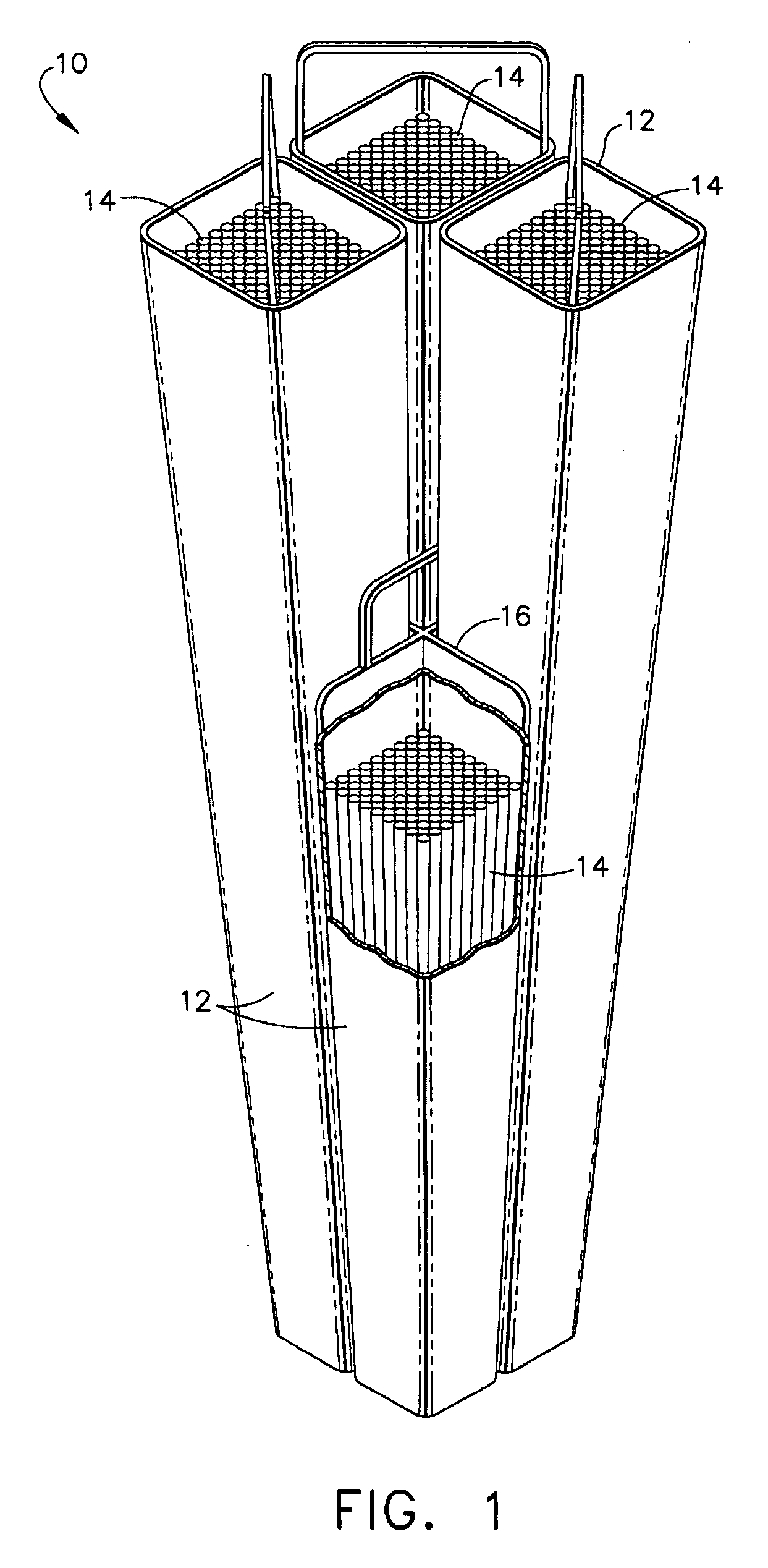
[0010] The exemplary flow channel construction materials according to the invention exhibit a reduced likelihood of deformation, even when subjected to non-uniform exposures including, differential irradiation, differential corrosion-induced hydrogen pickup, and possibly creep, while providing reduced sensitivity to cold work induced irradiation growth acceleration. An exemplar

Problems solved by technology

It has been shown that interference between a flow channel and an associated control blade can result from deformation, specifically bowing, of the flow channel as a result of non-uniformity, particularly side-to-side differences, in the irradiation-induced growth or the hydrogen content of the flow channel material.
Bowing from all sources is additive, and therefore the adverse effect of shadow corrosion bowing is exacerbated when irradiation growth, a phenomenon resulting from exposure to differential radiation gradients is also occurring in the control blade and flow channel components.
The service life of a boiling water reactor (BWR) fuel channel is generally limited by the ability of the channel to resist longitudinal bowing, creep and corrosion.
While the longitudinal bow may not be en

Method used


Image

  • LWR flow channel with reduced susceptibility to deformation and control blade interference under exposure to neutron radiation and corrosion fields
  • LWR flow channel with reduced susceptibility to deformation and control blade interference under exposure to neutron radiation and corrosion fields
  • LWR flow channel with reduced susceptibility to deformation and control blade interference under exposure to neutron radiation and corrosion fields

Examples


example 1

[0067] Operating of a fuel channel (flow box) in the outer regions of a BWR core results in a gradient of accumulated fast fluence in opposite channel faces. This differential fast fluence accumulation, in turn, results in differential irradiation growth of the opposite channel faces that tends to deform, specifically to bow, the channel. If the bowing of the fuel channel becomes excessive, the control rod positioned between adjacent channels can become “pinched” or bound between the two channels to a degree sufficient to impair control rod motion. In extreme cases, this friction force can be sufficient to cause the control rod to become inoperable, i.e., to freeze, the control rod.

[0068] Because the control rod provided in conjunction with an array of fuel rods performs an important safety function, its ability to operate all control rods at all times through their full range of motion is an important safety and operational consideration. Considering an operating history of a conv...

example 2

[0070] Alloy E635 is known within the nuclear industry as a low irradiation growth alloy, and therefore offers the performance advantages of a low growth alloy. However, the irradiation growth performance of NSF has been proven superior to alloy E635. Based on test reactor irradiations and corresponding irradiation growth measurements taken at multiple times during irradiation, the relative performance of NSF and E635 is known. Channel bow is determined by the rate of change of irradiation growth during the later periods of the operating lifetime of the channel. Comparing the measured rate of change of irradiation growth of alloy E635 and NSF over the same accumulated fast fluence interval that corresponds to the latter ˜50% of the channel lifetime, the relative channel bow performance of NSF and E635 can be determined. FIG. 3 presents this performance comparison. In FIG. 3, a lower value of the performance index represents less channel bow and correspondingly improved performance. ...

example 3

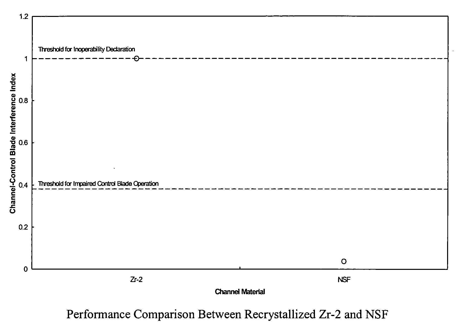
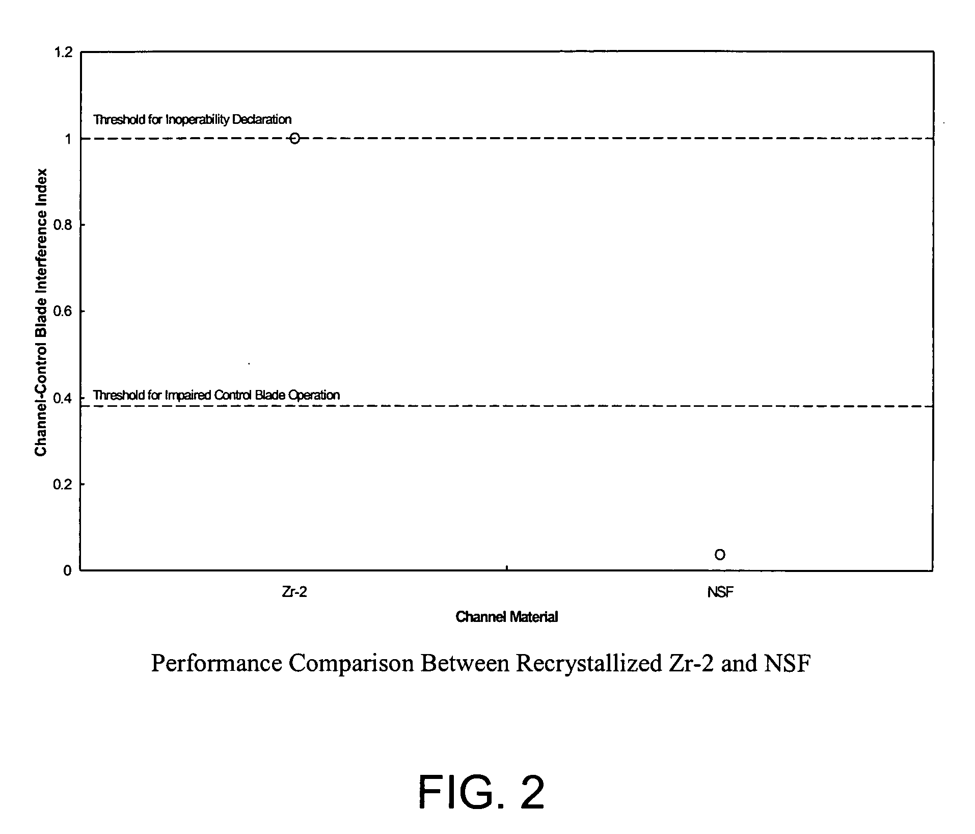
[0071] Channel fabrication requires the application of processing steps that can induce cold work into the material. Historically, instances have occurred with Zircaloy-2 channels where an excessive amount of cold work resulted in irradiation growth induced dimensional instability of sufficient magnitude to result in significant channel bow and impaired control rod motion. Based on the measured irradiation growth characteristics of recrystallized Zircaloy-2 and NSF, an assessment similar to that presented in FIG. 3 can be performed. FIG. 4 presents the results of that assessment indicating the substantial inherent tolerance of the NSF material to the effects of cold work of the magnitude that has caused significant channel performance effects with recrystallized Zircaloy-2.


PUM


Abstract

A zirconium alloy suitable for forming reactor components that exhibit reduced irradiation growth and improved corrosion resistance during operation of a light water reactor (LWR), for example, a boiling water reactor (BWR). During operation of the reactor, the reactor components will be exposed to a strong, and frequently asymmetrical, radiation fields sufficient to induce or accelerate corrosion of the irradiated alloy surfaces within the reactor core. Reactor components fabricated from the disclosed zirconium alloy will also tend to exhibit an improved tolerance for cold-working during fabrication of the component, thereby simplifying the fabrication of such components by reducing or eliminating subsequent thermal processing, for example, anneals, without unduly degrading the performance of the finished component.

Description

BACKGROUND OF THE INVENTION [0001] The present invention relates to materials and methods for eliminating or reducing the likelihood of interference between reactor components, for example, a flow channel and an associated control blade, in a nuclear reactor core so that the shutdown and operation of the plant can be performed more efficiently and safely. Channels used in the nuclear energy industry are typically formed from the zirconium alloys, such as Zircaloy-2 and Zircaloy-4, which have relatively high general corrosion resistance, but which are also known to be susceptible to bowing. It has been shown that interference between a flow channel and an associated control blade can result from deformation, specifically bowing, of the flow channel as a result of non-uniformity, particularly side-to-side differences, in the irradiation-induced growth or the hydrogen content of the flow channel material. [0002] These differences in the hydrogen content have recently been discovered to...

Claims


Application Information

Patent Timeline
IPC IPC(8): G21C1/04
CPCG21C3/07G21C3/324G21Y2002/203Y02E30/40G21Y2004/10G21Y2004/201G21Y2002/207Y02E30/30
Inventor LUTZ, DANIEL REESEPOTTS, GERALD ALLENLIN, YANG-PIMAHMOOD, SHEIKH TAHIRDUBECKY, MARK ANDREWWHITE, DAVID WILLIAMSCHARDT, JOHN
Owner GENERAL ELECTRIC CO
Why Eureka
Try Eureka