Mask, film forming method, light-emitting device, and electronic apparatus

a technology of light-emitting devices and masks, which is applied in the direction of cathode ray tubes/electron beam tubes, vacuum evaporation coatings, coatings, etc., can solve the problems of deteriorating emission efficiency, and reducing the emission efficiency of organic el elements of light-emitting devices. , to achieve the effect of preventing deformation of the mask

Inactive Publication Date: 2007-07-12
SEIKO EPSON CORP
View PDF6 Cites 66 Cited by
  • Summary
  • Abstract
  • Description
  • Claims
  • Application Information

AI Technical Summary

Benefits of technology

[0012]An advantage of the present invention is that it provides a mask which is used in a vapor deposition method and which can form a linear member such as a negative electrode with high dimensional precision, a film forming method of forming a linear member using the mask, and a light-emitting device and an electronic apparatus with excellent characteristics the linear member of which is formed by the film forming method.
[0014]According to an aspect of the invention, there is provided a mask which is used to form on the surface of a substrate a plurality of linear film members disposed in parallel to each other by fixing one surface of the mask to the substrate and supplying a film material through the other surface of the mask by the use of a vapor process. Here, the mask includes: a mask body having a plurality of openings corresponding to patterns of the linear film members; and reinforcement ribs which are disposed to cross the openings and which have a function of preventing deformation of the mask body due to the weight thereof. The reinforcement ribs are disposed close to the other surface of the mask in the thickness direction of the openings.
[0015]Accordingly, it is possible to provide a mask which is used in a vapor deposition method and which can form a linear member such as a negative electrode with high dimensional precision.
[0016]In the mask according to the aspect of the invention, the mask body and the reinforcement ribs may be formed in a body.
[0017]Accordingly, it is possible to form the mask body and the reinforcement ribs in a bundle and to form a mask with high dimensional precision. That is, it is possible to reduce the number of processes at the time of forming the mask and to surely obtain a mask with high dimensional precision.
[0018]The mask according to the aspect of the invention may be formed of silicon as a major component.

Problems solved by technology

Accordingly, there is a problem that the organic semiconductor layers reform and deteriorate due to the moisture or the like with the lapse of time and characteristics of the organic EL element such as emission efficiency deteriorate.
As a result, the characteristics such as the emission efficiency of the organic EL elements of a light-emitting device are not uniform.
Such a problem occurs similarly, for example, when a plurality of narrow metal interconnections arranged in parallel to each other are formed in a bundle using a vapor deposition method.

Method used


Image

  • Mask, film forming method, light-emitting device, and electronic apparatus
  • Mask, film forming method, light-emitting device, and electronic apparatus
  • Mask, film forming method, light-emitting device, and electronic apparatus

Examples


first embodiment

[0061]A mask according to a first embodiment of the invention will be described.

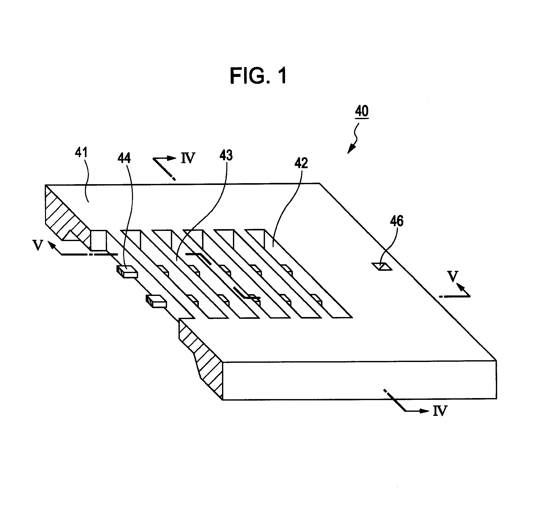
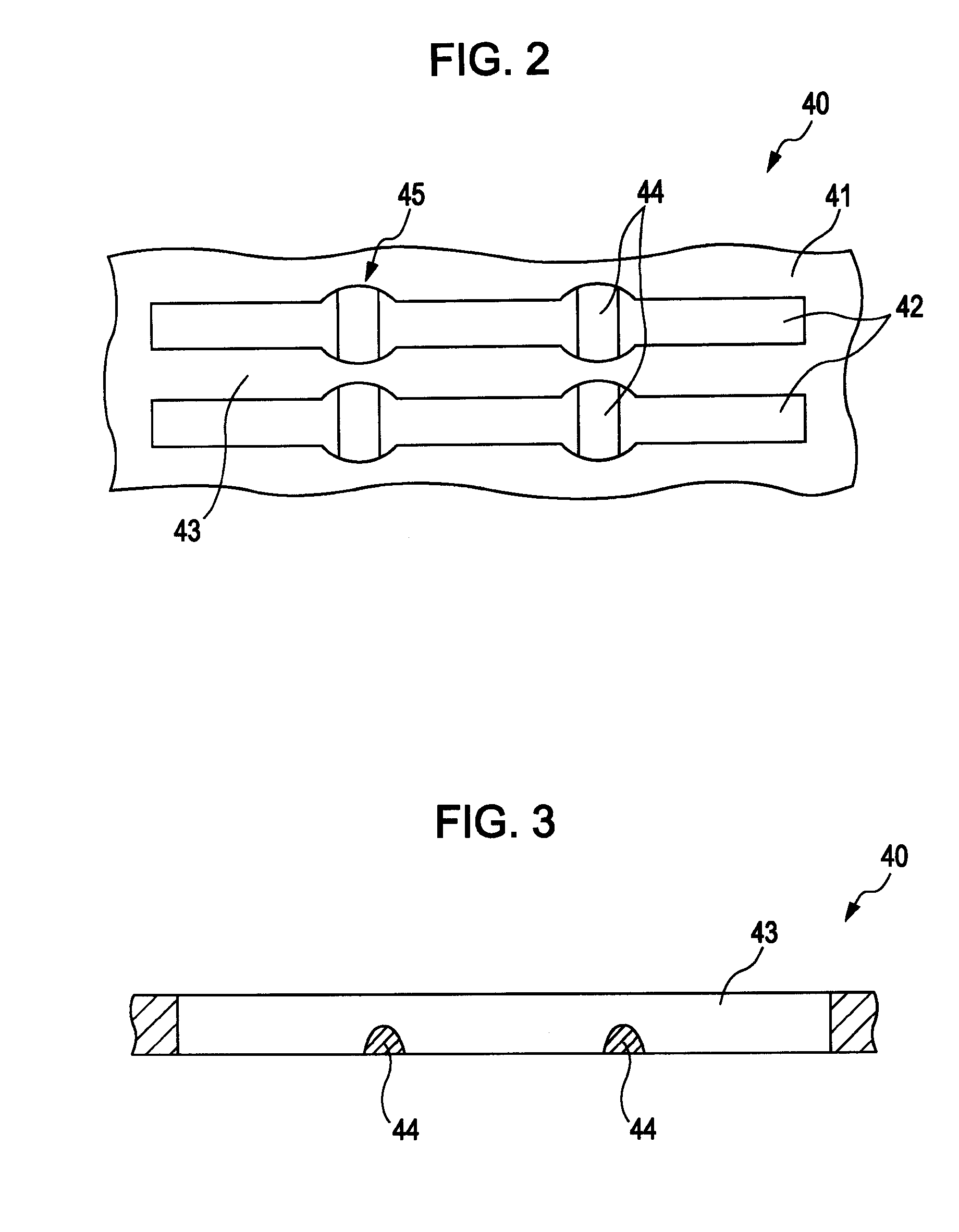
[0062]FIG. 1 is a perspective view illustrating a mask according to a first embodiment of the present invention, FIG. 2 is a plan view illustrating another configuration of openings, and FIG. 3 is a longitudinal sectional view illustrating another configuration of reinforcement ribs. In the following description, the upper side in FIGS. 1 and 3 is referred to as a “top” side and the lower side is referred to as a “bottom” side.

[0063]The mask according to the first embodiment of the invention is used to form on the surface of a substrate a plurality of linear film members disposed almost parallel to each other by fixing one surface thereof to the substrate and supplying a film material through the other surface by the use of a vapor deposition process such as a physical vapor deposition (PVD) method, for example, a vacuum deposition method, a sputtering method, and an ion plating method, or a chemical vap...

second embodiment

[0115]Next, a mask according to a second embodiment of the invention will be described.

[0116]FIG. 6 is a perspective view illustrating a mask according to the second embodiment of the invention. In the following description, the upper side in FIG. 6 is referred to as a top side and the lower side is referred to as a bottom side.

[0117]Differences between the second embodiment and the first embodiment are mainly described and like structures are not described.

[0118]The mask 40 shown in FIG. 6 is similar to the mask 40 according to the first embodiment, except that a metal layer 47 is formed on the top surface.

[0119]In the second embodiment, as shown in FIG. 6, a metal layer 47 is formed on the top surface, that is, on the surface of the mask body 41 contacting the substrate when the mask 40 is mounted on the substrate. As a result, by applying a magnetic field between the mask 40 and the substrate at the time of mounting the mask 40 on the substrate, it is possible to accomplish the i...

example 1

1B

[0278]First, the mask (A) was mounted on a quartz glass substrate and then the quartz glass having the mask (A) was set on a substrate holder in a chamber.

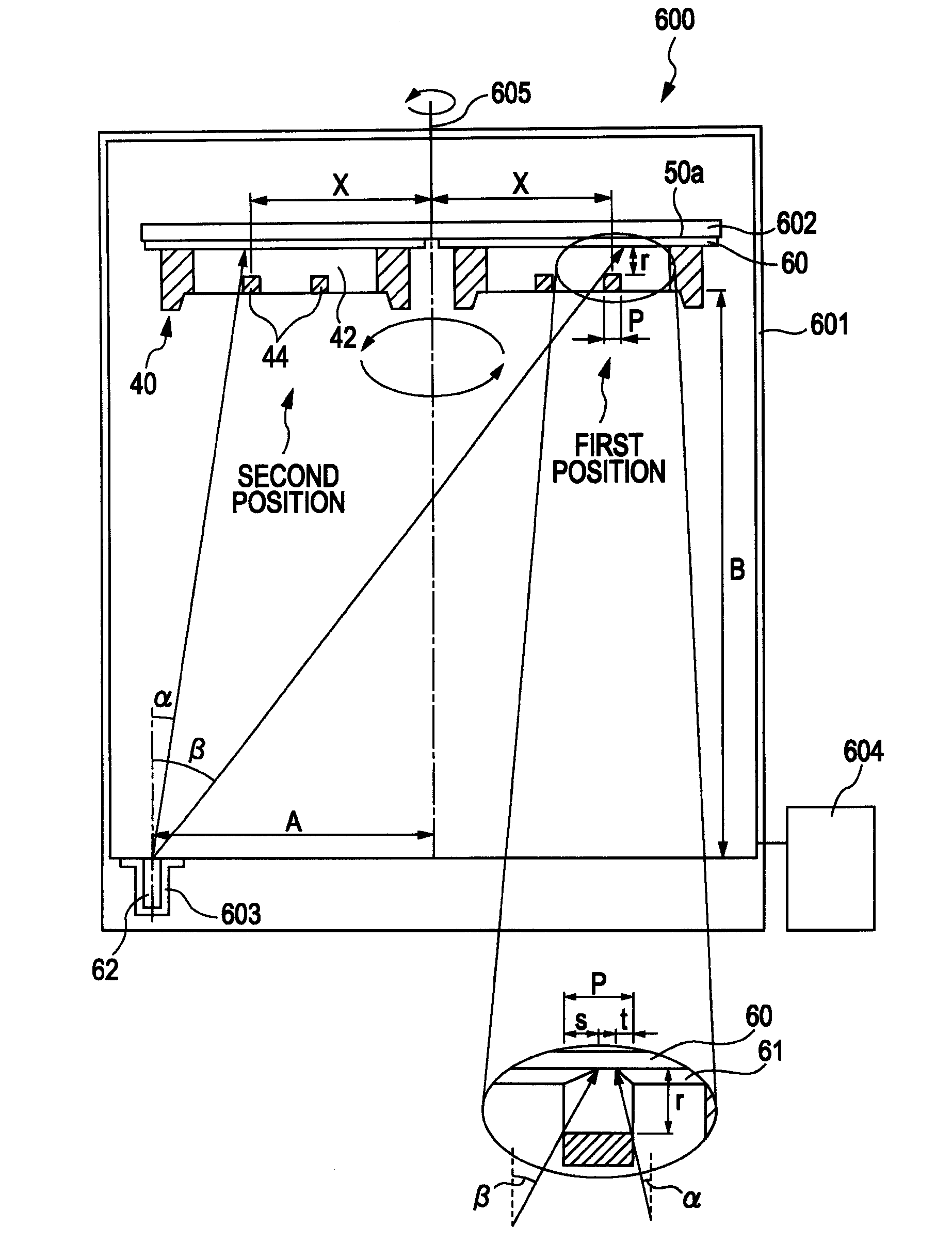
[0279]Then, Al was set in a crucible as a film material.

[0280]At this time, the distance A between a rotation axis of the substrate holder and a central axis of the crucible was set to 10.0 cm and the distance B between the mask (A) and the opening of the crucible was set to 20.0 cm.

2B

[0281]Next, an exhaust pump was operated so that the pressure within the chamber was set to 1×10⁻³ Pa.

3B

[0282]Next, the rotation axis of the substrate holder was rotated so that the quartz glass substrate (mask (A)) rotated at 10 rpm.

4B

[0283]Next, while rotating the quartz glass substrate, the crucible was heated to 1200° C. and the A1 was evaporated so that the linear member having an average thickness of 150 nm and using Al as a main material was formed on the quartz glass substrate.


PUM

PropertyMeasurementUnit
brightnessaaaaaaaaaa
thicknessaaaaaaaaaa
thicknessaaaaaaaaaa

Abstract

Provided is a mask which is used to form on the surface of a substrate a plurality of linear film members disposed in parallel to each other by fixing one surface of the mask to the substrate and supplying a film material through the other surface of the mask by the use of a vapor process. The mask includes: a mask body having a plurality of openings corresponding to patterns of the linear film members; and reinforcement ribs which are disposed to cross the openings and which have a function of preventing deformation of the mask body due to the weight thereof. Here, the reinforcement ribs are disposed close to the other surface of the mask in the thickness direction of the openings.

Description

BACKGROUND[0001]1. Technical Field[0002]The present invention relates to a mask, a film forming method, a light-emitting device, and an electronic apparatus.[0003]2. Related Art[0004]An organic EL element has a configuration in which a light-emitting layer including at least a fluorescent organic compound (light-emitting material) is disposed between a negative electrode and a positive electrode. The organic EL element generates excitons by injecting electrons and holes into the light-emitting layer, the electrons and the holes are then recombined, and light (fluorescence / phosphorescence) is emitted when the exciton activity decreases.[0005]The organic EL element has characteristics that it can perform surface emission with a high brightness in the range of 100 to 100,000 cd / m2 at a low voltage of 10V or less and that it can emit blue to red light in accordance with the light-emitting material used. The organic EL element has attracted attention as an element to be provided in a dis...

Claims


Application Information

Patent Timeline
Patent Type & Authority Applications(United States)
IPC IPC(8): B05C11/11H01J29/80
CPCH05B33/10C23C14/042
Inventor YOTSUYA, SHINICHI
Owner SEIKO EPSON CORP
Why Eureka
Try Eureka