Focused ion beam processing method

a processing method and focused ion beam technology, applied in the field of focused ion beam processing method, can solve the problems of reducing the intensity of applied laser light, irradiating objects such as transmissive photomasks, irradiation light transmittance, etc., to prevent the reduction of transmittance of the transmissive layer, reduce the damage to the workpiece, and reduce the effect of transmittan

Active Publication Date: 2007-07-12
HITACHI HIGH TECH SCI CORP
View PDF2 Cites 4 Cited by
  • Summary
  • Abstract
  • Description
  • Claims
  • Application Information

AI Technical Summary

Benefits of technology

[0019] The focused ion beam processing method according to the invention can prevent reduction in transmittance of the transmissive layer of the transmissive photomask, or reduction in reflectance of the reflective layer of the reflective mask. Therefore, these masks can be used with irradiation light with a short wavelength, which is from at least 13.5 nm to less than 248 nm, without any problem.
[0020] According to the focused ion beam processing method of the invention, when a workpiece is irradiated with an ion beam, ions are prevented from penetrating into the workpiece, so that damage to the workpiece can be minimized. For example, in repairing a transmissive photomask, reduction in transmittance can be avoided, while in repairing a reflective mask, reduction in reflectance can be avoided. Thus, even when irradiation light with a short wavelength is used, impact of the process can be minimized, allowing patterning of a line with a width narrower than or equal to 65 nm.

Problems solved by technology

In recent years, however, there has been a problem that an irradiated object, such as a transmissive photomask, gets damaged through irradiation of the focused ion beam.
There has been reported a problem in repairing a transmissive photomask, that is, ions of the focused ion beam that penetrate a transmissive layer (SiO2, for example) during irradiation reduce the transmittance of irradiation light to be applied in a transfer process.
However, according to the non-patent document 1, as shown in FIG. 7, the above-mentioned method for repairing a transmissive photomask does not contribute to sufficient improvement in transmittance of laser light with a wavelength less than 248 nm, and the repaired portion may unfortunately be transferred in the transfer process in semiconductor manufacturing.
Consequently, in a phase-effect mask utilizing a phase effect, mutual laser light interference unfortunately reduces the intensity of applied laser light.
Such a problem of damaged portion formation due to a focused ion beam also applies to a reflective mask in which irradiation light (EUV) is reflected for the purpose of transfer.
That is, when an absorption layer of a reflective mask is repaired with a focused ion beam, the reflectance of a reflection layer is unfortunately reduced.

Method used


Image

  • Focused ion beam processing method
  • Focused ion beam processing method
  • Focused ion beam processing method

Examples


first embodiment

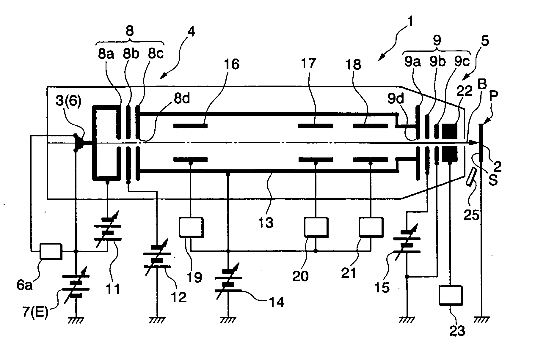
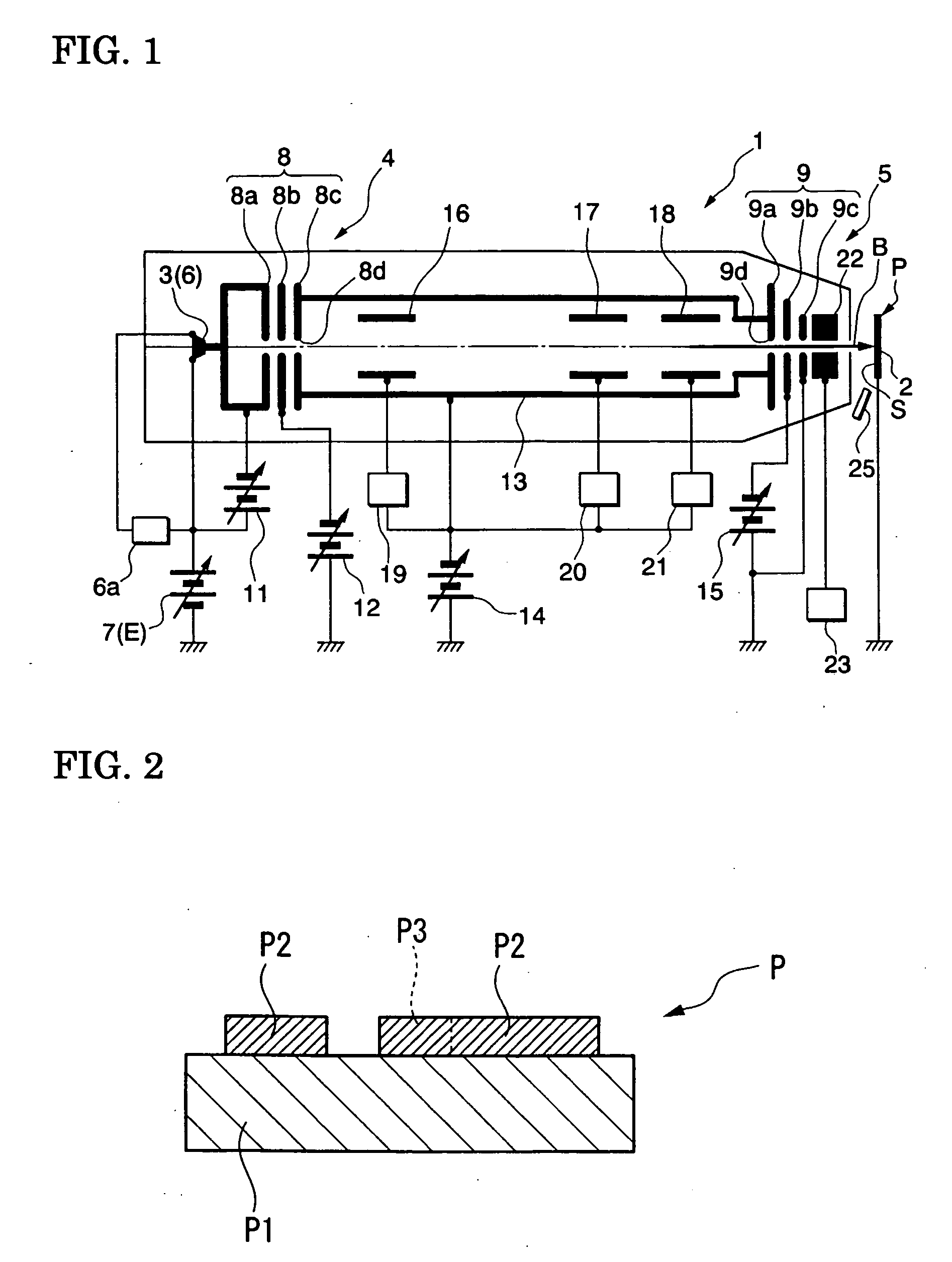
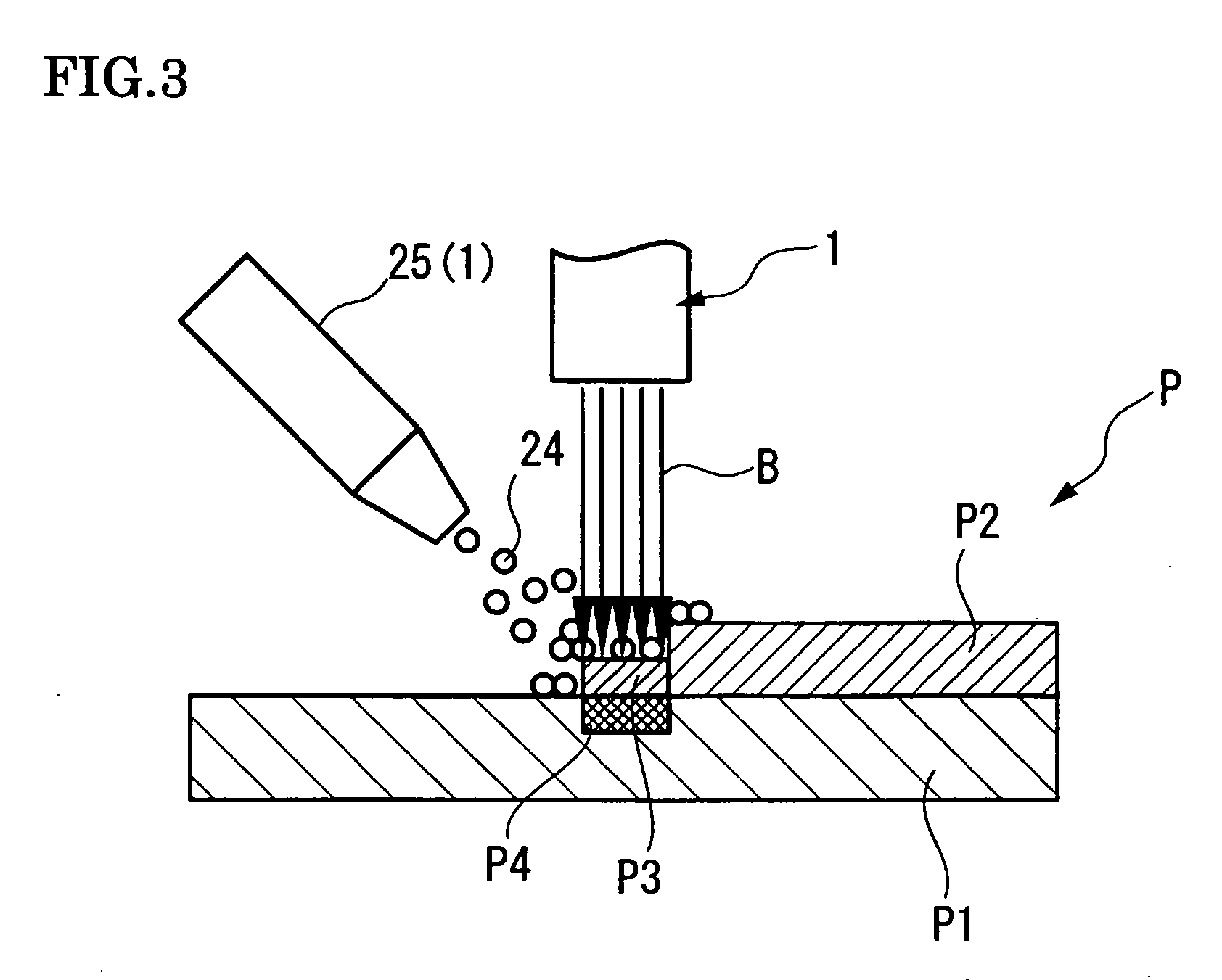
[0028] FIGS. 1 to 5 show a first embodiment according to the invention. FIG. 1 shows the configuration of a focused ion beam apparatus. FIG. 2 is a cross-sectional view of a transmissive photomask. FIG. 3 explains how the transmissive photomask is irradiated with the ion beam from the focused ion beam apparatus. FIG. 4 shows graphs illustrating the relationship between the depth of a damaged portion of a workpiece and the concentration of ions when the workpiece is irradiated with ion beams with various energy levels. FIG. 5 shows graphs illustrating the relationship between the energy level of ion beam irradiation and the post-irradiation transmittance of the transmissive photomask before and after a washing process.

[0029] As shown in FIG. 1, the focused ion beam apparatus 1 includes a workpiece mount 2 on which a transmissive photomask P, which is a workpiece, is mounted, an ion supply 3 that supplies an ion beam B with which the surface S of the transmissive photomask P is irrad...

second embodiment

[0039]FIG. 6 shows a second embodiment according to the invention and is a cross-sectional view of a reflective mask. In this embodiment, members common to those used in the above embodiment have the same characters and the description thereof will be omitted.

[0040] As shown in FIG. 6, the reflective mask Q includes a reflective layer Q1 that reflects irradiation laser light (irradiation light), an interference layer Q2 formed on the reflective layer Q1, and an absorption layer Q3 that is patterned on the interference layer Q2 and absorbs the irradiation laser light. More specifically, the reflective layer Q1 is a stacked structure of a plurality of layers made of silicon and a plurality of layers made of molybdenum. The interference layer Q2 is made of, for example, chromium. The absorption layer Q3 is made of, for example, a tantalum-based compound.

[0041] In such a reflective mask Q, the repair location Q4 (process position) of the patterned absorption layer Q3 can also be irrad...


PUM


Abstract

There is provided a focused ion beam processing method in which damage to a workpiece is minimized when the surface of the workpiece is irradiated and processed with an ion beam. The method comprises the steps of: generating an acceleration voltage between an ion source and a workpiece; focusing an ion beam emitted from the ion source; and applying the ion beam to a predetermined process position to process the surface of the workpiece. In this process, the energy level of the ion beam produced by the acceleration voltage is set within a range from at least 1 keV to less than 20 keV.

Description

[0001] This application claims priority under 35 U.S.C. §119 to Japanese Patent Application No. JP2005-289717 filed Oct. 3, 2005, the entire content of which is hereby incorporated by reference. BACKGROUND OF THE INVENTION [0002] 1. Field of the Invention [0003] The present invention relates to a focused ion beam processing method in which a focused ion beam is applied to microstructures such as new materials, semiconductor devices, photomasks, X-ray masks, storage devices, and magnetic heads for processing or observation thereof. [0004] 2. Description of the Related Art [0005] Conventionally, to repair a transmissive photomask, the location to be repaired is irradiated with a focused ion beam for processing. To improve processability, the focused ion beam is at an energy level of about 30 keV and has a beam diameter of 30 nm or smaller for nanometer processing in a quick and highly precise manner (see, for example, JP-A-2001-6605). In recent years, however, there has been a problem...

Claims


Application Information

Patent Timeline
Patent Type & Authority Applications(United States)
IPC IPC(8): H01J37/08
CPCG03F1/74H01J2237/31749H01J2237/31744
Inventor HAGIWARA, RYOJISUGIYAMA, YASUHIKOKOZAKAI, TOMOKAZU
Owner HITACHI HIGH TECH SCI CORP
Why Eureka
Try Eureka