Power generating system

a power generation system and power source technology, applied in the direction of mechanical energy handling, mechanical equipment, machines/engines, etc., can solve the problems of limited power, heavy battery pack, short duration, etc., to reduce the lateral movement of the mice generator, dampen the sound, and control the effect of excess vibration

Active Publication Date: 2007-07-12
AERODYNE RES
View PDF25 Cites 63 Cited by
  • Summary
  • Abstract
  • Description
  • Claims
  • Application Information

AI Technical Summary

Benefits of technology

[0016] The MICE generator is vibration-isolated using a base plate or other support surface that supports the MICE generator on a plurality of soft coil springs. In a typical embodiment the springs are oriented beneath the MICE generator relative to the vector of gravity. The springs can be conically shaped having a wider end at the base in one embodiment to reduce lateral movement of the MICE generator. Additional springs can be attached between a MICE generator enclosure and the MICE generator along its sides and / or top to further isolate and control excess vibration.
[0017] To damp sound generated by combustion, the MICE generator exhaust port can be interconnected with a muffler that is, typically, tuned to the frequency of combustion at steady state operation. The muffler can be attached in close proximity to the MICE generator or can be located remote therefrom, interconnected by an exhaust tube having a dampening covering (acoustic foam for example) thereon. The MICE generator is encased in an acoustic enclosure having a shell composed of sheet metal or another stiff material extending from the base plate and being covered by a top side. The shell includes a layer of dampening material on its interior and also its exterior and appropriate head-shielding where needed. The acoustic enclosure is generally sealed except for the outlet(s) for exhaust and inlets for fuel / air mixture and electrical leads. Where the muffler is located remotely, the outlet for exhaust can consist of a through hole for an exhaust tube that leads out of the acoustic enclosure. Where the muffler is in close proximity to the MICE generator, residing within the acoustic enclosure, the outlet consists of one or more holes that can be formed in the top of the acoustic enclosure. These holes are covered by porous discs that allow exhaust gasses from the internal muffler to pass therethrough, but dampen sound from combustion. The fuel / air inlet tube receives the fuel in atomized form, mixed with air, and delivers it to an intake plenum, which is heated to further volatilize the mixture as described above. In an illustrative embodiment, the fuel inlet and any associated electrical leads (alternator coil input / output, sensor leads, etc.) are staked at the MICE generator frame and at the base plate, typically adjacent to the acoustic enclosure and free of engagement by any structure therebetween. In this manner, as the MICE generator oscillates relative to the base, the lines between these two stake points flex with a large radius of curvature and low stress while the lines between the MICE generator frame and the MICE generator attachment points move essentially as a solid body minimizing the risk of stress and fatigue failure over time.
[0018] The acoustic enclosure resides in a large, typically portable, external package enclosure. The external package enclosure includes a layer of sound-dampening material around its interior. It can be vented to allow exhaust and / or heat (from for example heat exchangers) to be expelled to the environment. One or more fans can be employed to draw environmental air through the enclosure. An internal air intake (more isolated from dirt and debris, receives some of the drawn-in air. The external package enclosure can support an internal fuel tank and exhaust port, or these can be located externally and joined by conduits (in, for example, a vehicle-borne application). The enclosure contains, generally, a battery or other electric-power-storage unit for startup power; a fuel pump and atomizer; a control circuitry for sensing engine condition (temperature, power output, etc.) and varying fuel pump speed, cooling, heating, and the like; a power conditioning circuit for converting AC generator power into an appropriate voltage AC or DC power; an external panel that indicates status and includes a start button and one or more outlets for connecting devices to the power output; a coolant reservoir, heat exchanger and coolant pump with fluid tubing to and from the MICE generator ported through the acoustic enclosure; and various sub-enclosures (such as a sealed electronics enclosure) to protect internal components against water, exhaust, dirt and vibration.

Problems solved by technology

Each of these prior art approaches has limitations.
In the first type, the battery packs are heavy, have limited power, and short duration (in normal use, after one hour or so the battery pack needs to be removed and recharged).
For the second type, traditional fuel-powered motor-generators (Diesel or Otto cycle-type) using rotary crank shafts and pistons are heavy, noisy, and not particularly portable, and therefore impractical in many applications that require frequent movement, often on foot through rough terrain.
The typical motor generator used on a field construction site may be quite large and heavy to lift.
Its construction and weight do not lend themselves to frequent movement and / or placement close to the device.
These prior art motor generators are large because, while the average is power is not high (less than 50-200 watts), the peak power output may be many times larger while a device is actually operating.
However, such automotive-sized components (engine generator and batteries) are significantly larger than needed for most field applications (a few watts (W) to 1-2 kW) they do not scale down well.
However, conventional designs have a high weight to power out ratio.

Method used


Image

  • Power generating system
  • Power generating system
  • Power generating system

Examples


Embodiment Construction

[0044] A. Operating Cycle of a MICE Generator

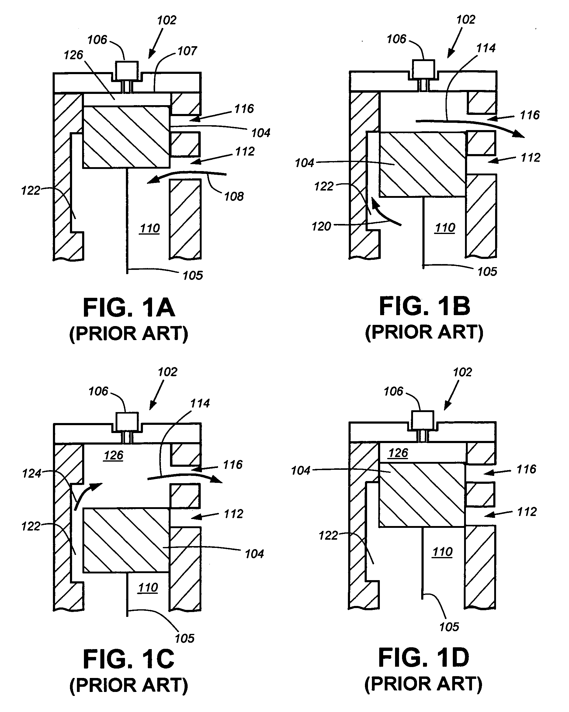
[0045] To further illustrate the operative principles of the MICE generator of this invention, reference is first made to FIGS. 1A-1D, which illustrate the operation of a typical two-cycle engine, such as those found in a small-scale model airplane.

[0046]FIG. 1A shows the cylinder head 102 of a two-cycle engine with a ringless piston 104 that drives a piston rod 105, shown at the top of its stroke. A glow plug 106 provides the ignition source during startup, and optionally during steady operation, to existing fuel / air mixture that is compressed in the space of the upper chamber 126 between the piston 104 and the top 107 of the cylinder head 102. As the piston 104 moves toward the top of the stroke, fuel-vapor / air mixture (represented by arrow 108) is contemporaneously drawn into the lower chamber 110 via an inlet port 112.

[0047]FIG. 1B shows the piston 104 after completion of the power portion of the expansion stroke that delivers powe...


PUM


Abstract

This invention overcomes the disadvantages of the prior art by providing a power generating system particularly suitable for field use in remote locations, which is fuel-efficient, relatively quiet, tolerant of dust, capable of operating on low grade logistics and diesel-like fuels and capable of generating between 500 W and 2 KW of continuous electrical power. This generator employs a miniature internal combustion engine/generator (MICE) having a piston moving within a cylinder arranged for two-cycle operation, and an interconnected, axially arranged piston shaft that oscillates an alternator coil within a magnetic core. The piston shaft is opposed by a strong, multiple-helix spring. The cylinder head, in which the piston operates, is cooled by moving (electrically pumped) fluid in a cooling head, or by another heat-transfer mechanism. The MICE generator's intake arrangement includes a preheater heated by a heated fluid flow thereon. The MICE generator is vibration-isolated using a base that supports the MICE on a plurality of soft coil springs. The MICE generator is encased in an acoustic enclosure having a shell composed of sheet metal or another stiff material extending from the base plate and being covered by a top side. Holes in the enclosure top are covered by porous discs that allow exhaust gasses from the internal muffler to pass therethrough. The acoustic enclosure resides in a large, typically portable, external package enclosure.

Description

RELATED APPLICATIONS [0001] This application is related to commonly owned copending U.S. patent application Ser. No. [Attorney Docket No. 016435-0036], entitled SYSTEM AND METHOD FOR CONTROLLING A POWER GENERATING SYSTEM, filed on even date herewith, by Kurt D. Annen, et al., which is expressly incorporated herein by reference.STATEMENT REGARDING FEDERALLY SUPPORTED RESEARCH OR DEVELOPMENT [0002] This invention was made with government support under Small Business Innovation Research awards: H92222-05-P-0028 and DAAB-03-C-0011. The government has certain rights in this invention.BACKGROUND OF THE INVENTION [0003] 1. Field of the Invention [0004] The present application relates to small portable power sources and more particularly to small combustion motor generator power sources. [0005] 2. Background Information [0006] For over a century there has been a need to generate electric power in the field, away from a reliable source of continuous power, such as the utility grid. Remotely ...

Claims


Application Information

Patent Timeline
Patent Type & Authority Applications(United States)
IPC IPC(8): H02K7/18F03G7/08F02B63/04
CPCF02B71/04H02K35/04H02K7/1884F02B2075/025
Inventor ANNEN, KURT D.WOODROFFE, JAIMEAGNESE, MICHAELSTICKLER, DAVID B.
Owner AERODYNE RES
Why Eureka
Try Eureka