
Process for the catalytic hydrotretment of heavy hydrocarbons of petroleum

a petroleum and hydrotretment technology, applied in the oil refining industry, hydrocarbon oil treatment, liquid hydrocarbon mixture production, etc., can solve the problems of limited operation of hydrotreatment processes of heavy hydrocarbons of petroleum at low pressure, >, etc., and achieve the effect of improving properties and high removal capacity

Active Publication Date: 2007-08-16
INST MEXICANO DEL GASOLINEEO
View PDF7 Cites 30 Cited by
  • Summary
  • Abstract
  • Description
  • Claims
  • Application Information

AI Technical Summary

Benefits of technology

[0049] The principal advantage of the present invention is that the process of catalytic hydrotreatment of heavy hydrocarbons of petroleum, which present an API gravity lower than 25° and a content of distillates recovered @ 538° C. lower than 80% by volume, is carried out by the combination of low-pressure operating conditions, of the type of reactor and of the type of feedstock to be hydrotreated, which together provide a high capacity for removal of metals, sulfur, nitrogen and asphaltenes, as well as limiting the formation of sediments and sludge, to obtain a hydrotreated hydrocarbon of improved properties. The low-pressure operating conditions, in which the process of the present invention is carried out are, generally, those presented in Frame I, where as for each reaction stage there are specific or preferably ranges of low-pressure operating conditions as presented in Frames II and III respectively.
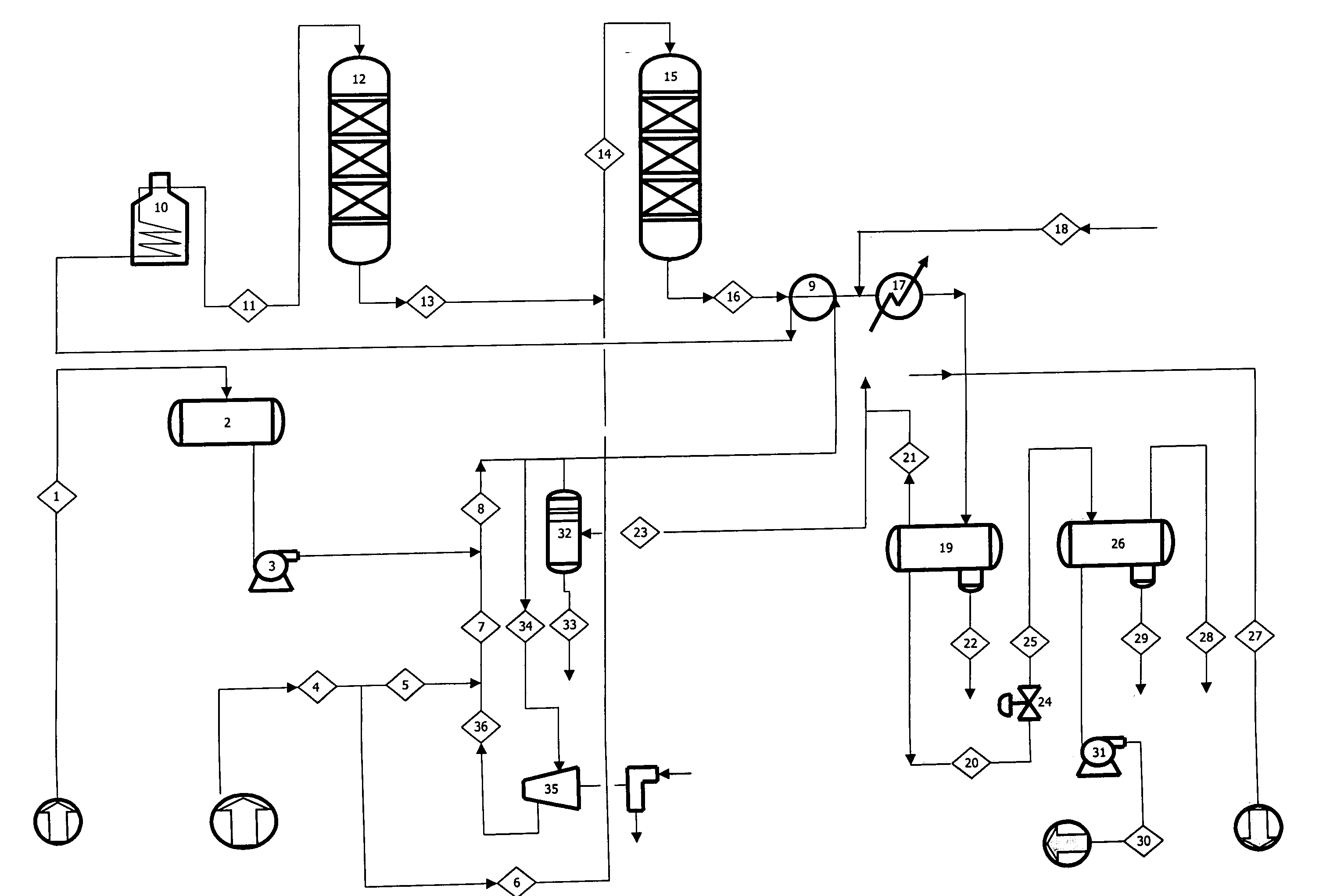
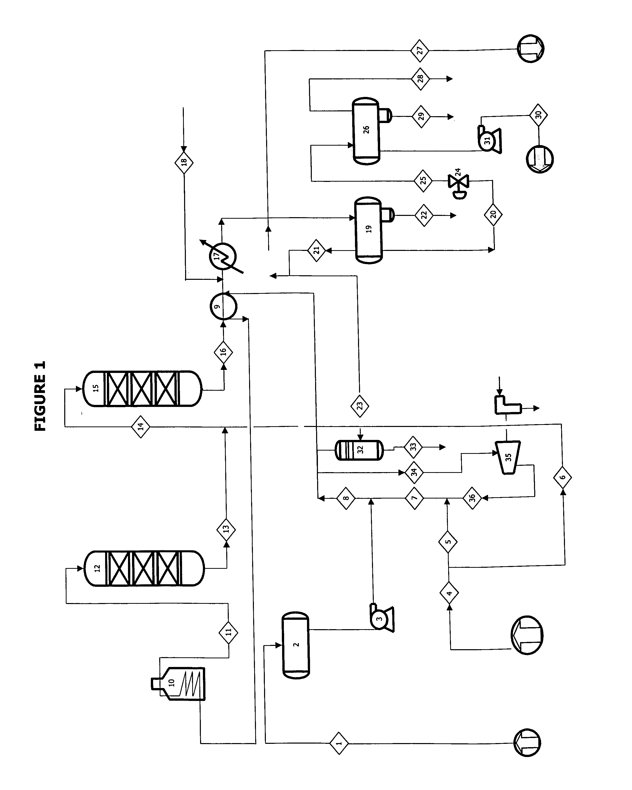
[0050] Specifically, described below is the flow chart of FIG. 1 which illustrates the best way known to the applicant for carrying out the process proposed in the present invention:
[0051] The heavy hydrocarbon of petroleum indicated in the line (1), is introduced to a feed tank (2), and is conducted through the pump (3) in order to be mixed with the hydrogen indicated with the line (7), which is constituted by a part of the fresh hydrogen (5) and recycle hydrogen (36).
[0052] The fresh hydrogen indicated by the line (4) is divided into two parts, the first part (5) is injected together with the recycle hydrogen (36) to the heavy hydrocarbon of petroleum (1), to be conducted mixed (8) to the catalytic reactor of stage I (12); and the second part (6) is sent to a the catalytic reactor of stage III (15).
[0053] The feed mixture of hydrogen (8) is preheated with the effluent from the reactor (16) through a heat exchanger (9), to then raise its temperature by means of a direct fire heater (10). The heated effluent (11) is conducted to the catalytic reactor of stage I (12) at the reaction temperature indicated in Frame II, in order to carry out principally the reactions of hydrodemetallization and hydrocracking, as well as complementary reactions to a lesser degree of hydrodesulfurization and hydrodenitrogenation.
[0054] The product hydrotreated in the first reaction stage (13) is mixed with another part of the fresh hydrogen indicated by the line (6), in order to form a stream (14) that is introduced to the catalytic reactor of stage II (15), where principally the reactions of hydrodesulfurization and hydrodenitrogenation are carried out, as well as complementary reactions to a lesser degree of hydrodemetallization and hydrocracking, according to the low-pressure operating conditions indicated in Frame III.

Problems solved by technology

The heavy crudes require a treatment similar to the petroleum residuals for their processing, due to the fact that they are characterized by their low Hydrogen / Carbon (H / C) ratio, high viscosity, high content of contaminants, essentially sulfur, nitrogen and metals, and low yield of distillates.
The operation of the hydrotreatment processes of heavy hydrocarbons of petroleum at low pressures, less than 140 kg / cm2, has been limited by the formation of sediments and sludge, which is a characteristic problem of these processes.

Method used


Image

  • Process for the catalytic hydrotretment of heavy hydrocarbons of petroleum
  • Process for the catalytic hydrotretment of heavy hydrocarbons of petroleum
  • Process for the catalytic hydrotretment of heavy hydrocarbons of petroleum

Examples


example 1

[0061] A specific application of the process of catalytic hydrotreatment of heavy hydrocarbons of petroleum, the motive of the present invention, to obtain a typical feedstock for a conventional refining scheme or for its sale as a hydrocarbon of improved properties, is the one that was carried out on hydrotreating heavy crude with the specific properties that are presented in Table 1, through the combination of low-pressure operating conditions that are shown in Table 2, in two stages of fixed-bed reaction and the use of hydrodemetallization (HDM) and hydrodesulfurization catalysts (HDS), whose properties are presented in Table 3; which together demonstrate that although surprisingly they achieve significant removal of metals, total sulfur, asphaltenes and total nitrogen, the formation of sediments and sludge is unexpectedly limited, and the hydrotreated hydrocarbon of improved properties that is presented in Table 4 is obtained.

[0062] Table 1 shows that the feed does not contain ...

example 2

[0070] Another specific application of the process of catalytic hydrotreatment of heavy hydrocarbons of petroleum of the present invention, is the one which was carried out on hydrotreating the heavy crude of example 1, with the specific properties reported in Table 1, through the combination of low-pressure operating conditions that are shown in Table 5, in a catalytic system in two stages of fixed-bed reaction and the use of HDM and HDS catalysts of example 1, whose properties are presented in Table 3; which together demonstrate notably that the formation of sediments and sludge is limited, as well as attaining significant removals of metals, total sulfur, asphaltenes and total nitrogen, and obtaining the hydrotreated hydrocarbon of improved properties shown in Table 6.

[0071] Unlike the previous example, for this specific application of the invention, only the pressure was modified (to a lower value) and the space velocity (to a higher value) in the second reaction stage of the p...

example 3

[0076] Another specific application of the present invention, to obtain a typical feed for a conventional refining scheme or for its sale as a hydrocarbon of improved properties, was done by carrying out the catalytic hydrotreatment of the heavy crude of examples 1 and 2, with the specific properties reported in Table 1, through the combination of: the low-pressure operating conditions shown in Table 7, in a catalytic system in two stages of fixed-bed reaction and the use of HDM and HDS catalysts of examples 1 and 2, whose properties are shown in Table 3; which together demonstrate that the formation of sediments and sludge is limited, in addition to attaining significant removals of metals, total sulfur, asphaltenes and total nitrogen, and obtaining the hydrotreated hydrocarbon of improved properties shown in Table 8.

[0077] Unlike example 1, for this specific application of the invention, only the space velocity was-modified (to a higher value, as in example 2) in the second react...


PUM


Abstract

Two-stage low pressure catalytic hydrotreatment of heavy petroleum hydrocarbons having a high content of contaminants (metals and asphaltenes), is conducted under operating conditions with low-pressure, in a fixed bed or ebullated bed reactor to limit the formation of sediments and sludge in the product and obtain a hydrotreated hydrocarbon of improved properties, with levels of contaminants, API gravity and distillates within the ranges commonly reported in the feedstocks typical to refining schemes. A hydrotreatment catalyst, whose principal effect is the hydrodemetallization and the hydrocracking of asphaltenes of the heavy hydrocarbons of petroleum is used in the first stage, and the second reaction stage employs a hydrotreatment catalyst for a deeper effect of hydrodesulfurization of the heavy petroleum hydrocarbon whose content of total sulfur is reduced to a level required for its treatment in the conventional refining process or for its sale as a hydrocarbon of petroleum with improved properties.

Description

TECHNICAL FIELD OF THE INVENTION [0001] The present invention provides a process of the oil refining industry, in which a catalytic hydrotreatment of heavy hydrocarbons of petroleum is carried out in order to improve their properties. BACKGROUND OF THE INVENTION [0002] The evolution of the refining industry has lead to the hydrotreatment of heavy hydrocarbons of petroleum acquiring a technological and economic importance similar to the processes of hydrocracking and catalytic reforming. Among the heavy hydrocarbons of petroleum are the heavy crudes, the extra-heavy crudes, blends of heavy and light crudes and petroleum residuals, such as residues from the atmospheric or vacuum distillation, which present a specific gravity less than 32° API and a content of distillates recovered @ 538° C. less than 80% by volume. [0003] The production of heavy crudes and the availability of petroleum residuals with high sulfur and metal contents, as well as the demands regarding the improvement of f...

Claims


Application Information

Patent Timeline
Patent Type & Authority Applications(United States)
IPC IPC(8): C10G65/00C10G1/00C10G45/00C10G17/00C10G69/00C10G47/00C10G65/02C10G65/12
CPCC10G45/02C10G65/02C10G65/12C10G2300/4018C10G2300/1033C10G2300/107C10G2300/4012C10G2300/202C10G2300/205C10G2300/206C10G2300/308C10G2300/4006C10G2300/1077
Inventor ANCHEYTA JUAREZ, JORGEBETANCOURT RIVERA, GERARDOMARROQUIN SANCHEZ, GUSTAVOCENTENO NOLASCO, GUILLERMOMUNOZ MAYA, JOSE ANTONIO DOMINGOALONSO MARTINEZ, FERNANDO
Owner INST MEXICANO DEL GASOLINEEO
Learn More