
Process for industrial production of an aromatic carbonate

a technology of industrial production and aromatic carbonate, which is applied in the direction of separation process, carbonic/haloformic acid esters purification/separation, sustainable manufacturing/processing, etc., to achieve high selectivity and high purity

Active Publication Date: 2007-08-16
ASAHI KASEI KK
View PDF1 Cites 11 Cited by
  • Summary
  • Abstract
  • Description
  • Claims
  • Application Information

AI Technical Summary

Benefits of technology

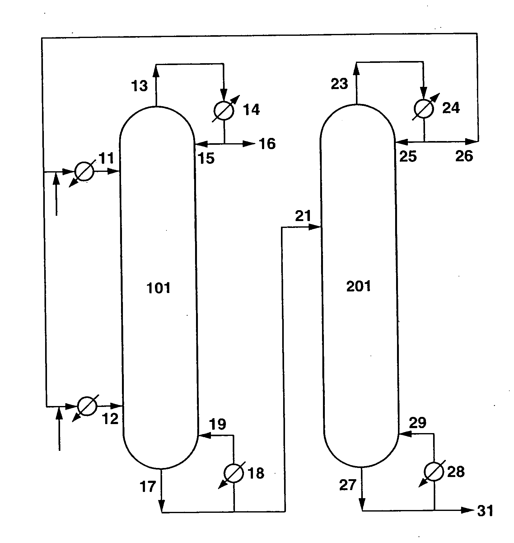
The present invention provides a process for producing aromatic carbonates containing a diaryl carbonate as a main product with high selectivity and productivity stably for a prolonged period of time on an industrial scale of not less than 1 ton per hour. The process involves a continuous multi-stage distillation column system using two continuous columns and a catalyst. The first column carries out a reaction between a dialkyl carbonate and an aromatic monohydroxy compound to produce an alcohol and an alkyl aryl carbonate. The second column carries out a reaction between the produced alcohol and another dialkyl carbonate to produce a dialkyl carbonate and a diaryl carbonate. The process is stable and efficient for mass production of aromatic carbonates on an industrial scale.

Problems solved by technology

However, these have all been on a small scale and short operating time laboratory level, and there have been no disclosures whatsoever on a specific process or apparatus enabling mass production on an industrial scale.

Method used


Image

  • Process for industrial production of an aromatic carbonate
  • Process for industrial production of an aromatic carbonate
  • Process for industrial production of an aromatic carbonate

Examples


example 1

101>

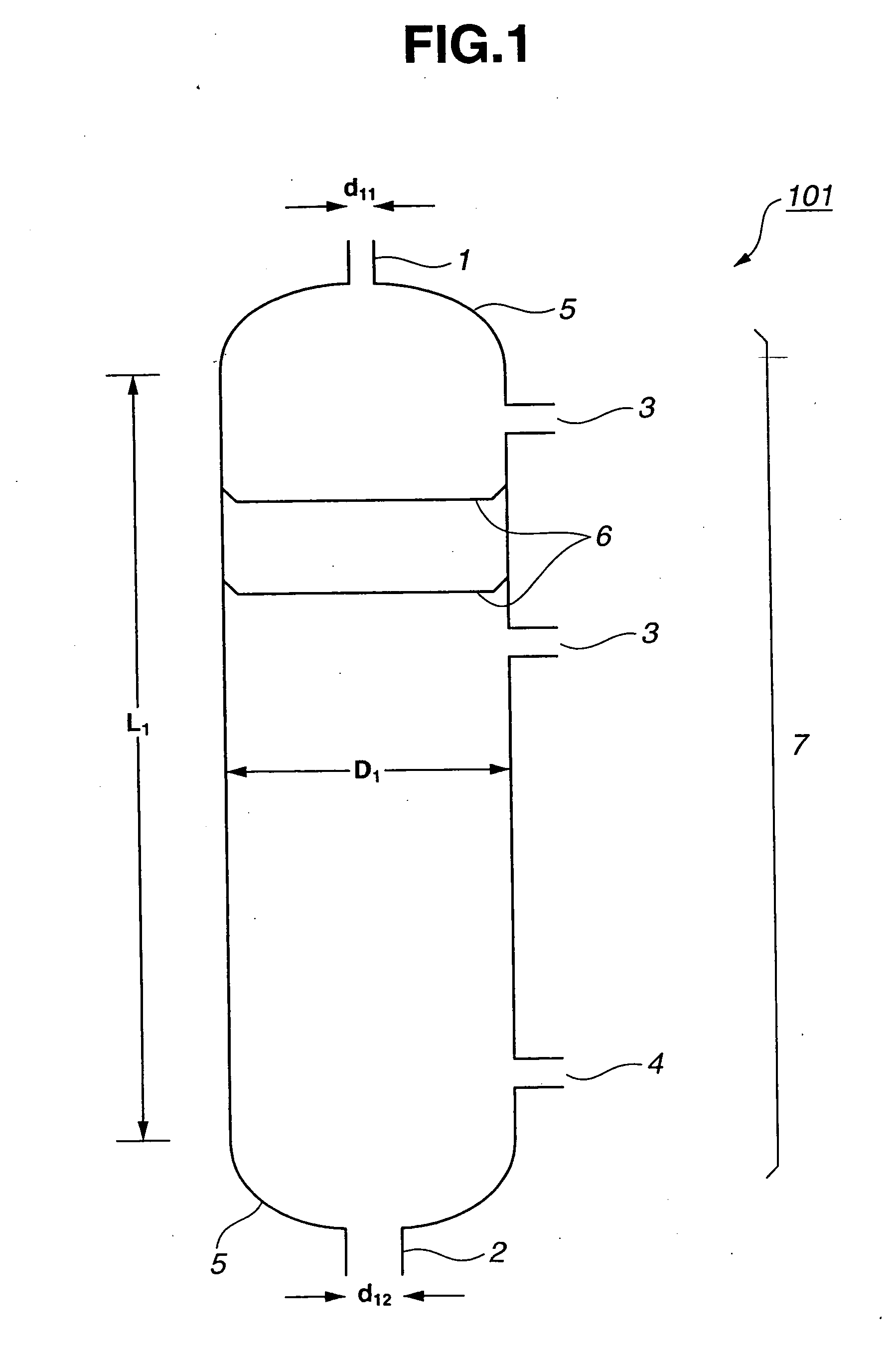
[0162] A continuous multi-stage distillation column as shown in FIG. 1 having L1=3300 cm, D1=500 cm, L1 / D1=6.6, n1=80, D1 / d11=17, and D1 / d12=9 was used. In this Example, the sieve tray having the cross-sectional area per hole being approximately 1.5 cm2 and the number of holes being approximately 250 / m2 were used as the internal.

201>

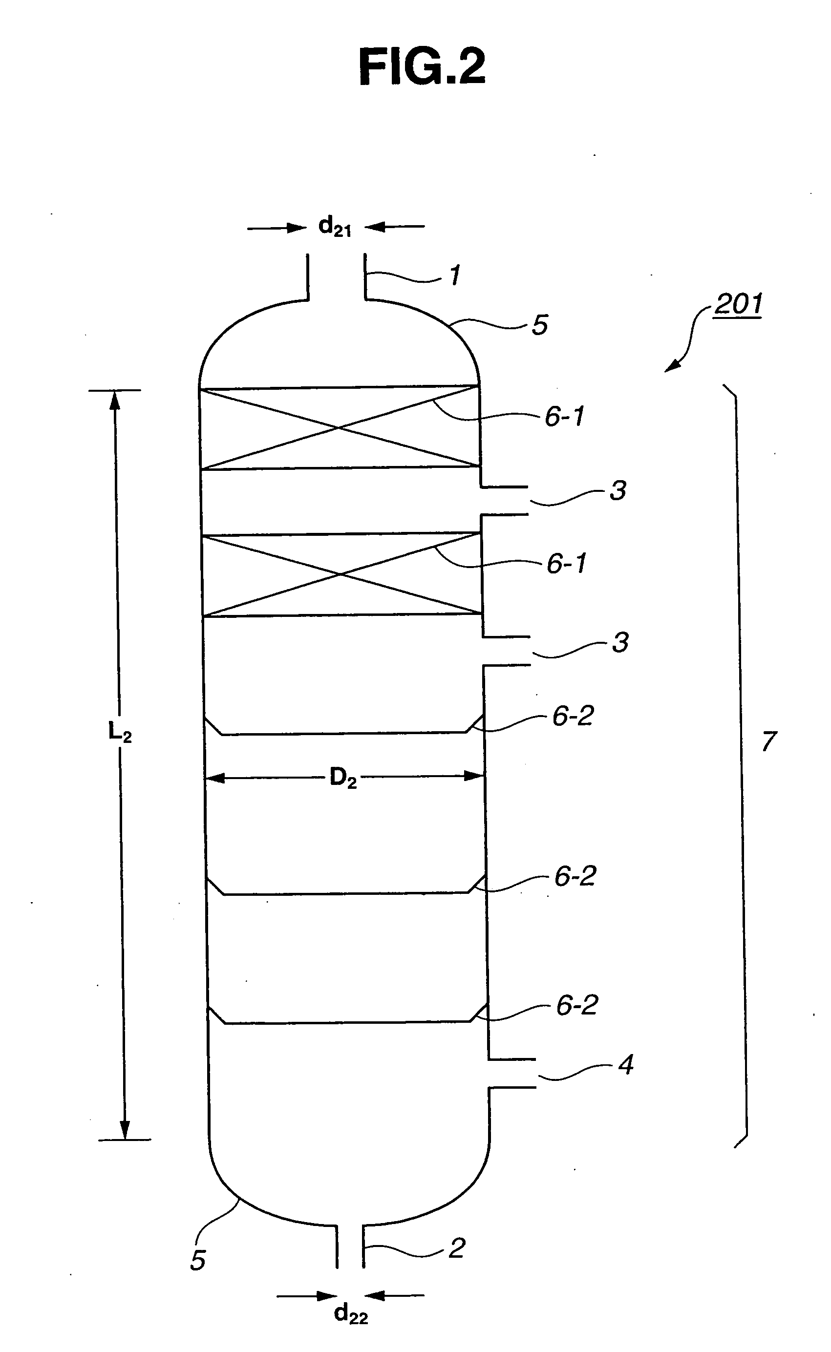
[0163] A continuous multi-stage distillation column as shown in FIG. 2 having L2=3100 cm, D2=500 cm, L2 / D2=6.2, n2=30, D2 / d21=3.85, and D2 / d22=11.1 was used. In this Example, as the internal, two sets of Mellapak (total number of stages 11) were installed in the upper portion, and the sieve tray having the cross-sectional area per hole being approximately 1.3 cm2 and the number of holes being approximately 250 / m2 were used in the lower portion.

[0164] Diphenyl carbonate was produced by carrying out reactive distillation using a apparatus in which the first continuous multi-stage distillation column 101 and the second continuous multi-stage distillat...

example 2

[0169] Reactive distillation was carried out under the following conditions using the same apparatus as in Example 1.

[0170] A starting material 1 containing phenol and dimethyl carbonate in a weight ratio of phenol / dimethyl carbonate=1.1 was introduced continuously in a liquid form at a flow rate of 40 ton / hr from the upper inlet 11 of the first continuous multi-stage distillation column 101. On the other hand, a starting material 2 containing dimethyl carbonate and phenol in a weight ratio of dimethyl carbonate / phenol=3.9 was introduced continuously in a gaseous form at a flow rate of 43 ton / hr from the lower inlet 12 of the first continuous multi-stage distillation column 101. The molar ratio for the starting materials introduced into the first continuous multi-stage distillation column 101 was dimethyl carbonate / phenol=1.87. The starting materials substantially did not contain halogens (outside the detection limit for the ion chromatography, i.e. 1 ppb or less). Pb(OPh)2 as a ca...

example 3

[0175] Reactive distillation was carried out under the following conditions using the same apparatus as in Example 1 except that the cross-sectional area per hole of each of the sieve trays in the second continuous multi-stage distillation column 201 was made to be approximately 1.8 cm2.

[0176] A starting material 1 containing phenol and dimethyl carbonate in a weight ratio of phenol / dimethyl carbonate=1.7 was introduced continuously in a liquid form at a flow rate of 86 ton / hr from the upper inlet 11 of the first continuous multi-stage distillation column 101. On the other hand, a starting material 2 containing dimethyl carbonate and phenol in a weight ratio of dimethyl carbonate / phenol=3.5 was introduced continuously in a gaseous form at a flow rate of 90 ton / hr from the lower inlet 12 of the first continuous multi-stage distillation column 101. The molar ratio for the starting materials introduced into the first continuous multi-stage distillation column 101 was dimethyl carbonat...


PUM

PropertyMeasurementUnit
cross-sectional areaaaaaaaaaaa
areaaaaaaaaaaa
areaaaaaaaaaaa

Abstract

It is an object of the present invention to provide a specific process that enables aromatic carbonates to be produced with high selectivity and high productivity stably for a prolonged period of time on an industrial scale of not less than 1 ton per hour from a dialkyl carbonate and an aromatic monohydroxy compound using two continuous multi-stage distillation columns. Although there have been various proposals regarding processes for the production of aromatic carbonates by means of a reactive distillation method, these have all been on a small scale and short operating time laboratory level, and there have been no disclosures whatsoever on a specific process or apparatus enabling mass production on an industrial scale. According to the present invention, there are provided two specified continuous multi-stage distillation columns, and there is also provided a specific process that enables aromatic carbonates to be produced with high selectivity and high productivity stably for a prolonged period of time on an industrial scale of not less than 1 ton per hour from a dialkyl carbonate and an aromatic monohydroxy compound using a apparatus in which these two continuous multi-stage distillation columns are connected together.

Description

TECHNICAL FIELD [0001] The present invention relates to an industrial process for the production of an aromatic carbonate. More particularly, the present invention relates to an industrial process for the production of a large amount of an aromatic carbonate containing a diaryl carbonate as a main product, which is useful as a raw material of a transesterification method polycarbonate by subjecting a dialkyl carbonate and an aromatic monohydroxy compound to transesterification reaction in two continuous multi-stage distillation columns in each of which a catalyst is present. BACKGROUND ART [0002] An aromatic carbonates is important as a raw material for the production of aromatic polycarbonate which is the most widely used engineering plastic, without using toxic phosgene. As a process for producing an aromatic carbonate, a process of reacting an aromatic monohydroxy compound with phosgene has been known from long ago, and has also been the subject of a variety of studies in recent ...

Claims


Application Information

Patent Timeline
Patent Type & Authority Applications(United States)
IPC IPC(8): C07C69/96
CPCB01D3/009B01D3/143B01D3/146C07C68/06C07C68/08C07C69/96Y02P20/10
Inventor FUKUOKA, SHINSUKEHACHIYA, HIROSHIMATSUZAKI, KAZUHIKO
Owner ASAHI KASEI KK
Learn More