Thread optimized multiprocessor architecture

a multi-processor and architecture technology, applied in memory systems, program control, instruments, etc., can solve the problems of limiting the application of very specialized applications, large time penalty, and rare maximum improvement, so as to increase the computer speed, and increase the instruction execution speed

Active Publication Date: 2007-08-16
BLANKENSHIP BETH
View PDF16 Cites 30 Cited by
  • Summary
  • Abstract
  • Description
  • Claims
  • Application Information

AI Technical Summary

Benefits of technology

[0002] Computer speed may be increased using two general approaches: increase instruction execution speed or do more instruction execution in parallel....

Problems solved by technology

Theoretical maximum improvement is seldom achieved due to the inefficiencies of multi-step instructions, inability of many software programs to provide enough sequential instructions to keep the parallel execution units filled, and the large time penalty paid when a branch, loop, or case construct is encountered requiring the refilling of the execution units.
The communications and interconnects necessary to support these arrays of processors inherently limits them to very specialized applications.
Heavily pipelined computers very seldom achieve performance anywhere near the theoretical performance improvement expected from the parallel pipeline execution units.
Any branch that changes program flow upsets the pipeline.
Attempts to minimize the pipeline upset tend to be complex and incomplete in their mitigation.
Arbitration for pipeline register and other resource access often reduces performance due to the propagation delays of the transistors in the arbitration logic.
Acceleration through parallelism is limited by overhead due to non-serializable portions of the problem.
Another inefficiency of current processors is the inability of scaling the computing power to meet the immediate computing demand.
This waiting is an inefficient waste of computing power.
Furthermore, the computer time spent waiting often results in increased power consumption and heat generation.
Increasing offs...

Method used


Image

  • Thread optimized multiprocessor architecture
  • Thread optimized multiprocessor architecture
  • Thread optimized multiprocessor architecture

Examples


Embodiment Construction

[0094] The TOMI architecture of at least one embodiment of the present invention preferably uses the minimum logic possible to operate as a general purpose computer. The most common operations are given priority. Most operations are visible, regular, and available for compiler optimization.

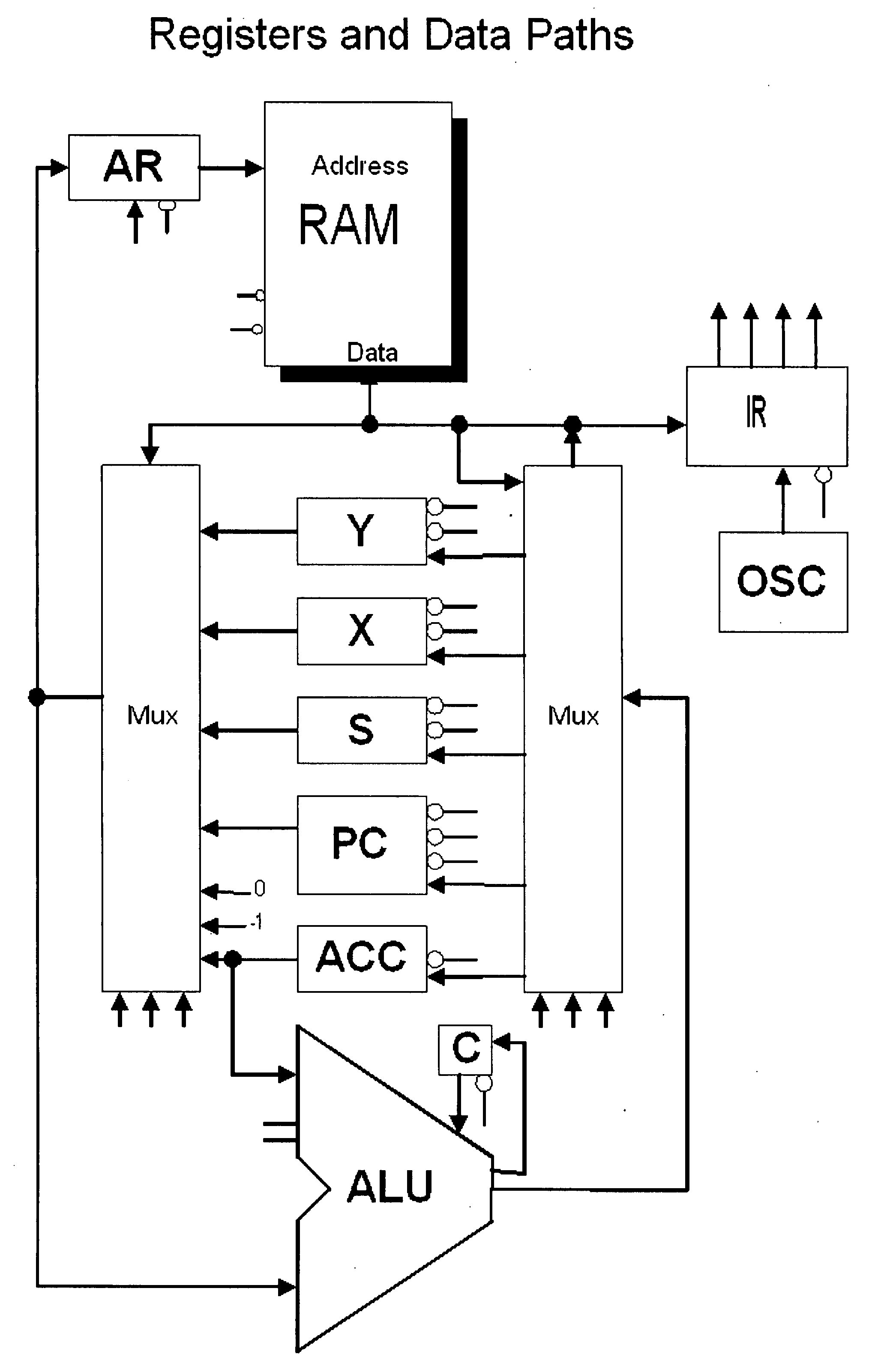
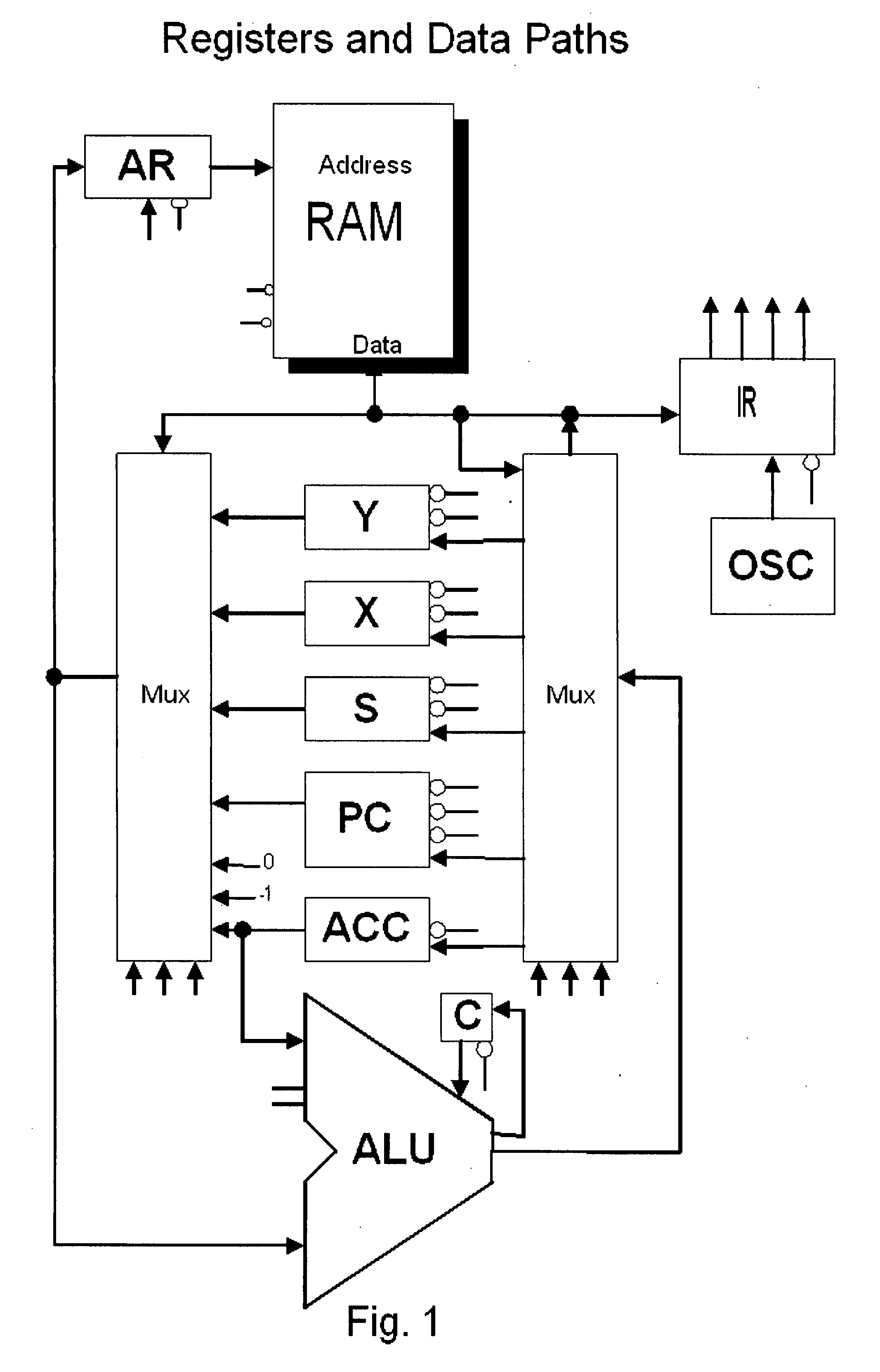
[0095] In one embodiment, the TOMI architecture is a variation on accumulator, register, and stack architectures, as illustrated in FIG. 1. In this embodiment:

[0096] 1. Like an accumulator architecture, the accumulator is always one of the operands, except for the increment instruction.

[0097] 2. Like a register architecture, the destination is always one of the operand registers.

[0098] 3. The accumulator and program counter are also in the register space and may therefore be operated on.

[0099] 4. Three special registers auto-increment and auto-decrement and are useful for creating stacks and streams of input and output.

[0100] 5. All operations require a single clock cycle (and two states: cl...


PUM


Abstract

In one aspect, the invention comprises a system comprising: (a) a plurality of parallel processors on a single chip; and (b) computer memory located on the chip and accessible by each of the processors; wherein each of the processors is operable to process a de minimis instruction set, and wherein each of the processors comprises local caches dedicated to each of at least three specific registers in the processor. In another aspect, the invention comprises a system comprising: (a) a plurality of parallel processors on a single chip; and (b) computer memory located on the chip and accessible by each of the processors, wherein each of the processors is operable to process an instruction set optimized for thread-level parallel processing.

Description

CROSS REFERENCE TO RELATED APPLICATIONS [0001] This application claims priority to U.S. Provisional Patent Application No. 60 / 764,955, filed Feb. 3, 2006. The entire contents of that provisional application are incorporated herein by reference.BACKGROUND AND SUMMARY [0002] Computer speed may be increased using two general approaches: increase instruction execution speed or do more instruction execution in parallel. As instruction execution speed approaches the limits of electron mobility in silicon, parallelism becomes the best alternative to increasing computer speed. [0003] Previous attempts at parallelism have included: [0004] 1. Overlapping next instruction fetching with current instruction execution. [0005] 2. Instruction pipelining. An instruction pipeline breaks each instruction into as many pieces as possible and then attempts to map sequential instructions into parallel execution units. Theoretical maximum improvement is seldom achieved due to the inefficiencies of multi-st...

Claims


Application Information

Patent Timeline
IPC IPC(8): G06F9/30
CPCG06F9/30138G06F9/30145G06F9/322G06F9/38G06F15/7846G06F9/3867G06F9/3885G06F9/3891G06F12/0875G06F9/3851G06F15/781G06F9/30G06F9/06
Inventor FISH, RUSSELL H. III
Owner BLANKENSHIP BETH
Why Eureka
Try Eureka