Medical x-ray detection device including an active optical signal emitter

Inactive Publication Date: 2007-08-23
BRAINLAB
View PDF8 Cites 10 Cited by
  • Summary
  • Abstract
  • Description
  • Claims
  • Application Information

AI Technical Summary

Benefits of technology

[0005] A signal emitter includes an active light-emitting signal means, and an x-ray detector, which is operatively coupled to the signal emitter. The x-ray detector can detect the start and / or end of x-ray radiation and provide the data to the signal emitter, wherein the signal emitter emits corresponding signals. In other words, the signal emitter emits an optical signal (e.g., active light emissions), which can be directly detected without time lag, such that the presence of the x-ray radiation can be reliably detected temporally.
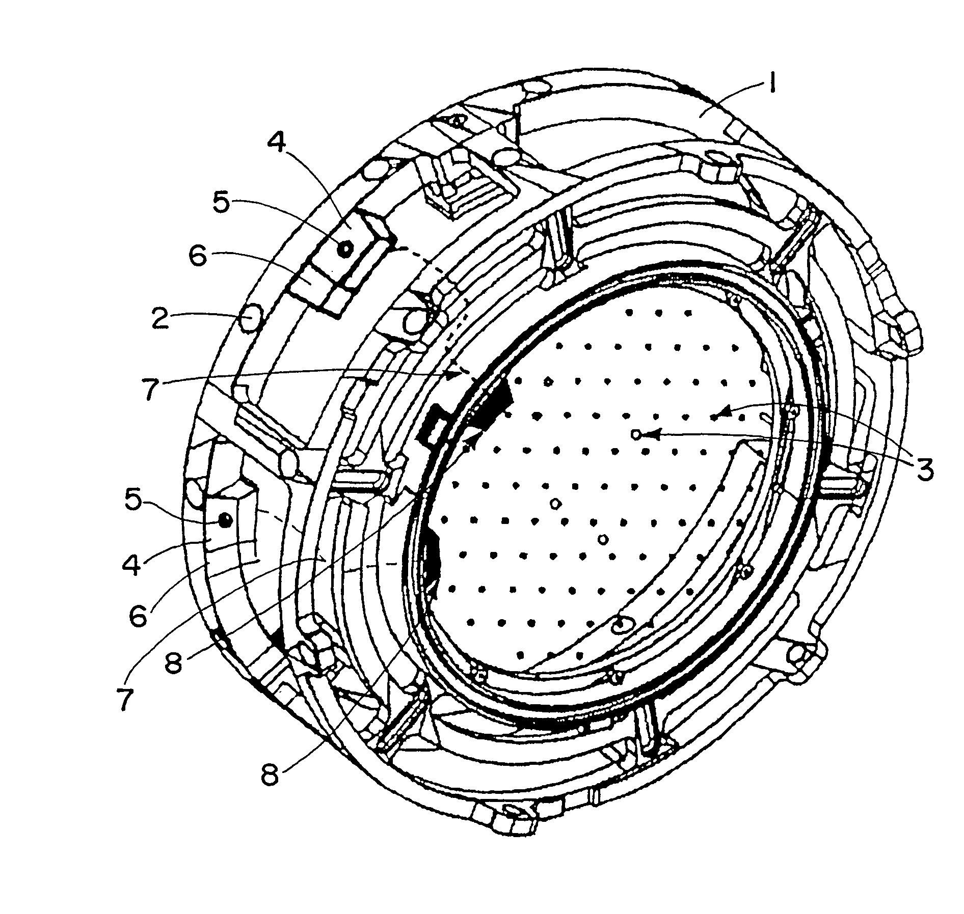
[0008] In accordance with another aspect of the invention, a medical x-ray detection system can include an x-ray detection device such as described herein. The x-ray detection system also can include a fluoroscopic image registration unit, wherein the x-ray detector and the signal emitter are arranged on the fluoroscopic image registration unit. It is then possible to arrange the x-ray detector in the radiation transmission path of the fluoroscopic image registration unit. The x-ray detector, for example, can be arranged at a point at which it can reliably detect the presence of x-ray radiation. The signal emitter can be advantageously arranged on the outside of the fluoroscopic image registration unit, thereby enabling signal emissions to be easily detected by other externally mounted devices.
[0011] Further, a medical x-ray detection system can be provided that includes an x-ray detection device as described herein, as well as an optical medical tracking system, such as an infrared tracking system. The signal emitter can be arranged within the detection range of the tracking system. This is advantageous as the optical signal emitter can be easily and directly incorporated into the tracking system environment. Since such optical tracking systems are available or used in many navigation environments, the detection signal can be easily detected, processed and integrated into the sequence. Such a system (comprising a tracking system) can of course also comprise the features described herein for the medical x-ray detection system.
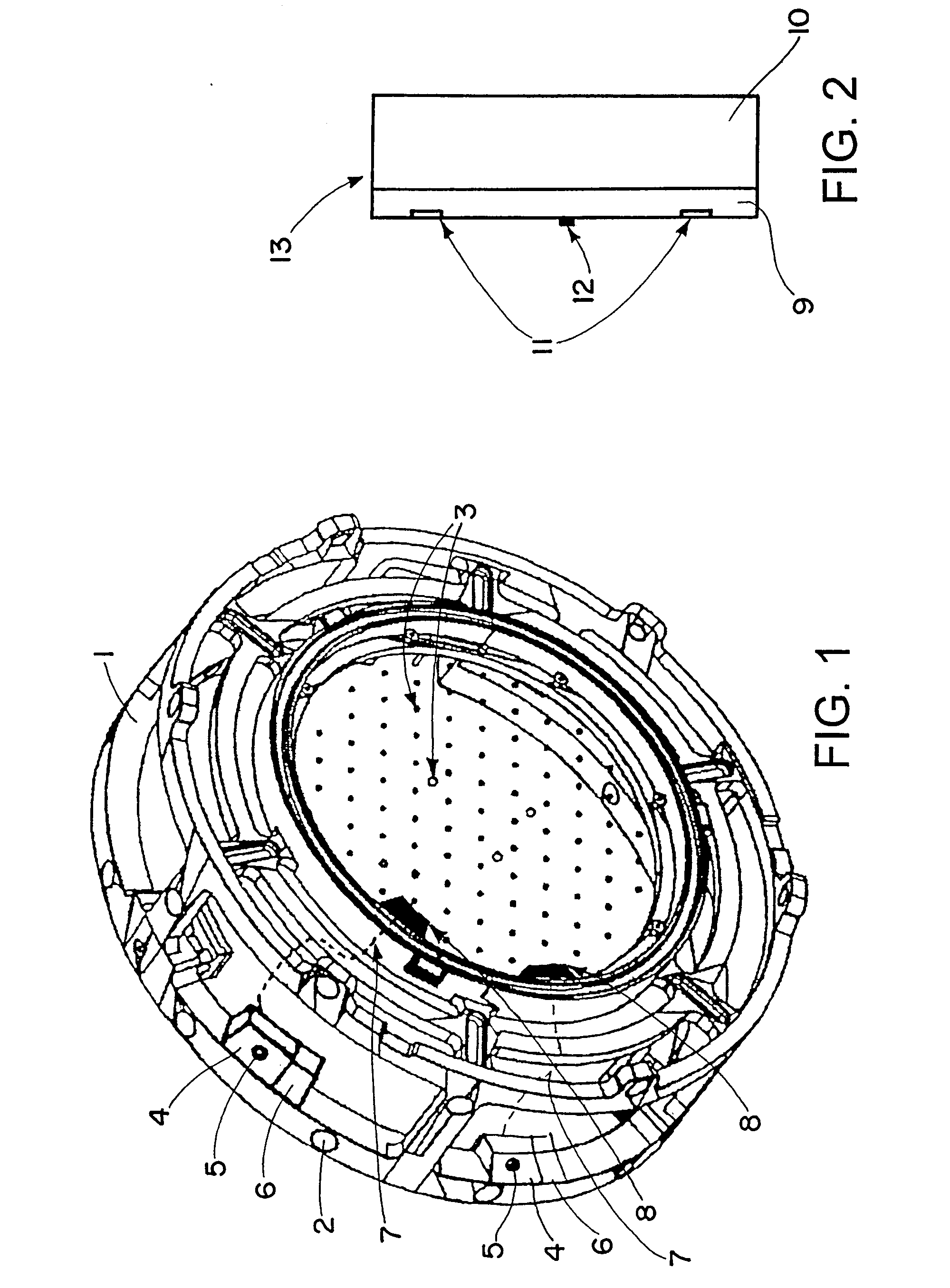
[0012] A method for x-ray detection includes detecting, via a detector unit, x-rays generated during treatment or treatment preparation. The information pertaining to the start and end of the radiation time can be relayed by an active component that can be embedded within an array of passive markers. The integration of passive and active light transmission is mutually supplemented here; both signals can be wirelessly transmitted and detected. While passive markers on a registration kit are perfectly sufficient for localizing such a kit, the active signal transmission for x-ray detection optimally supplements this information transmission. It is thus possible to incorporate trigger signals for the start or end of radiation, for example into a known navigation environment based on reflection marker technology. Integrating one or more x-ray detectors into the fluoroscopic image registration kit and supplementing the marker array of the kit with the signal emitter thus allows improved detection of newly acquired images, which incurs a high degree of reliability. Due to the control via this part of fluoroscopic image acquisition, all x-ray tracking or navigation systems can benefit from greatly reduced tracking errors. This applies to C-arm x-ray systems using analog image transmission (video), since the approach does not exhibit the drawbacks of purely software-based image comparison methods.
[0014] Specifically for C-arm fluoroscopy apparatus having an analog transmission mode, automatic signal detection may be quickly and easily implemented. When the x-ray radiation is detected, the information from the image comparison, for example, can be supplemented with the trigger signal of the signal emitter. The exact time for storing the tracking information then can be ascertained from the coincidence criterion, in accordance with which both processes must take place at the same time, and within a very small time interval. A way of obtaining correct tracking information, which is more reliable in this way, also increases the safety and security of the patients.

Problems solved by technology

Such cables, however, typically are laid or otherwise provided separate in the x-ray device or registration device and, therefore, necessitate additional interfaces on the signal receiving components, which increases overall system complexity.
Such a system is known, for example, from EP 1 260 179 B1; however, many older or specific operating x-ray apparatus are still in use whose signal-to-noise ratio makes such a procedure difficult to implement or does not permit such a procedure.
As a result, navigation problems may arise.

Method used


Image

  • Medical x-ray detection device including an active optical signal emitter
  • Medical x-ray detection device including an active optical signal emitter

Examples


Embodiment Construction

[0018] The registration kit 1 shown in FIG. 1 can be a circular attachment for a image intensifier of a C-arm x-ray apparatus (fluoroscope). The kit 1 can include an insert in the radiation transmission path comprising tungsten spheres 3 for the internal registration of the projective properties and several passive reflection markers 2. The markers 2 can be provided in a specific arrangement and enable tracking of the kit 1 within a tracking and navigation environment.

[0019] A tracking or navigation system 13 is schematically shown in FIG. 2. The system 13 can include a tracking system 9 and a navigation system 10 that processes and / or outputs tracking information (e.g., spatially localizing a treatment apparatus and a treatment-assisting apparatus, in particular spatially localizing and determining a location of the registration kit 1). The tracking system 9 can include two cameras 11 and an infrared emitter 12. Infrared light from the emitter 12, for example, can be reflected by ...


PUM


Abstract

A medical x-ray detection device includes an x-ray detector operable to detect the presence of x-ray radiation in a medical environment, and a signal emitter operatively coupled to said x-ray detector. The signal emitter includes at least one active light-emitting signal device, wherein the signal emitter is operative to emit a signal corresponding to the presence of x-ray radiation.

Description

RELATED APPLICATION DATA [0001] This application claims priority of U.S. Provisional Application No. 60 / 777,071 filed on Feb. 27, 2006, which is incorporated herein by reference in its entirety.FIELD OF THE INVENTION [0002] The invention relates to a medical x-ray detection method, device and system, wherein an x-ray detector detects the presence of x-ray radiation in a medical environment, and a signal emitter emits a signal with respect to the detected x-ray radiation. BACKGROUND OF THE INVENTION [0003] In many cases x-ray detection devices are used when registering x-ray images within the context of medical navigation. Such devices enable the determination of when (and therefore the relative position of the patient) the image was produced so as to allow the image to be correctly assigned within the context of navigation. It is of course in principle also possible to transmit the detection signal to a receiver via cable, e.g., to a further processing unit, such as a navigation sys...

Claims


Application Information

Patent Timeline
IPC IPC(8): H05G1/10
CPCA61B6/00A61B6/12A61B6/4441A61B2019/5255A61B19/5244A61B2019/5238A61B6/547A61B2034/2055A61B34/20A61B2090/376
Inventor BOGOJEVIC, ALEKSANDERWEISER, MANFRED
Owner BRAINLAB
Why Eureka
Try Eureka