Organic electroluminescent device

a technology of electroluminescent devices and organic materials, which is applied in the direction of thermoelectric devices, discharge tube luminescnet screens, natural mineral layered products, etc., can solve the problems of reducing light emission efficiency, serious quenching of light emission, and devices not yet developed to meet high efficiency and high durability. , to achieve the effect of high light emission efficiency and high durability

Active Publication Date: 2007-08-23
UDC IRELAND
View PDF2 Cites 37 Cited by
  • Summary
  • Abstract
  • Description
  • Claims
  • Application Information

AI Technical Summary

Benefits of technology

[0007]An object of the present invention is to provide an organic electroluminescent device assured of high light emission efficiency and high durability.

Problems solved by technology

There have been disclosed inventions related to a phosphorescent device using an iridium complex, a platinum complex (see, U.S. Pat. No. 6,303,238 and International Publication 00 / 57676, pamphlet) or the like as the phosphorescent material, but a device satisfying both high efficiency and high durability has not yet been developed.
However, the materials used therein have a condensed ring or a long conjugate system and all are low in the lowest excited triplet level (T1 level) of molecule and when used for a phosphorescent device, such a material quenches the light emitted from the phosphorescent material to decrease the light emission efficiency.
This is prominent in the emission of light at a short wavelength, and serious quenching of light emission occurs particularly on use for a blue phosphorescent device.

Method used


Image

  • Organic electroluminescent device
  • Organic electroluminescent device
  • Organic electroluminescent device

Examples


synthesis example 1

Synthesis of Compound 1

[0094]

[0095]In a nitrogen atmosphere, 1 g (3.21 mmol) of 2,2-dibromobiphenyl, 1.27 g (6.41 mmol) of 2-(4,4,5,5-tetramethyl-1,3,2-dioxaboran-2-yl)biphenyl, 168 mg (0.64 mmol) of triphenylphosphine, 2.39 g (17.3 mmol) of potassium carbonate, 36 mg (0.16 mmol) of palladium acetate, 20 mL of 1,2-dimethoxyethane and 30 mL of water were refluxed under heating for 2 hours. The obtained reaction mixture was extracted with ethyl acetate, and the organic layer was washed with saturated brine and dried over anhydrous magnesium sulfate. After removing the solvent by distillation under reduced pressure, recrystallization from an ethanol-chloroform mixed solvent was performed to obtain 0.70 g (yield: 48%) Compound 1 as a colorless cubic crystal.

synthesis example 2

Synthesis of Compound 165

[0096]

[0097]In a nitrogen atmosphere, 1.5 g (3.96 mmol) of Compound A, 3.0 g (15.82 mmol) of o-trifluoromethylphenylboric acid, 207 mg (0.79 mmol) of triphenylphosphine, 2.95 g (21.4 mmol) of potassium carbonate, 44 mg (0.20 mmol) of palladium acetate, 15 mL of 1,2-dimethoxyethane and 20 mL of water were refluxed under heating for 5 hours. The obtained reaction mixture was extracted with ethyl acetate, and the organic layer was washed with saturated brine and dried over anhydrous magnesium sulfate. After removing the solvent by distillation under reduced pressure, recrystallization from chloroform was performed to obtain 2.2 g (yield: 92%) Compound 165 as a colorless powder crystal.

[0098]Considering the durability of the device, the glass transition temperature (Tg) of the compound of the present invention is preferably from 130 to 450° C., more preferably from 135 to 450° C., still more preferably from 140 to 450° C., yet still more preferably from 150 to 4...

example 1

[0176]An organic electroluminescent device of Example 1 was produced in the same manner as the organic electroluminescent device of except for changing CBP to Compound 10 of the present invention.


PUM

PropertyMeasurementUnit
glass transition temperatureaaaaaaaaaa
Tgaaaaaaaaaa
Tgaaaaaaaaaa

Abstract

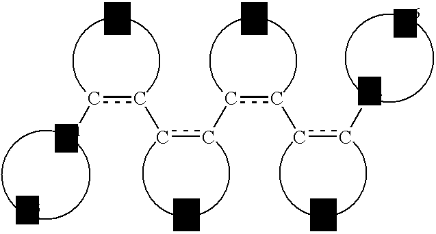
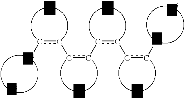
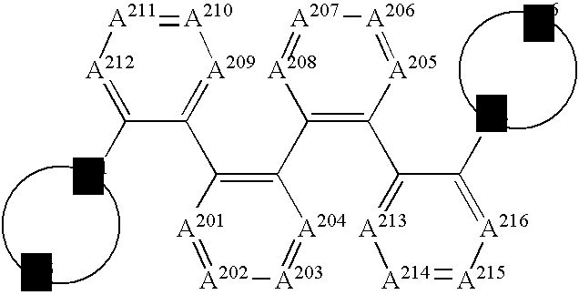
An organic electroluminescent device comprises: a pair of electrodes; and at least one organic compound layer therebetween, the at least one organic compound layer comprises at least a light-emitting layer, wherein at least one of the at least one organic compound layer comprises at least one compound represented by formula (1):
Formula (1):
wherein Q1 to Q4 each independently represents an atomic group for forming an aromatic hydrocarbon ring or an aromatic heterocyclic ring in combination with two carbon atoms in formula (1); A1 and A2 each independently represents a carbon atom or a nitrogen atom; and Q5 and Q6 each independently represents an atomic group for forming an aromatic hydrocarbon ring or an aromatic heterocyclic ring in combination with A1 and A2 respectively, provided that Q5 and Q6 are not combined through a single bond, a divalent aromatic hydrocarbon ring group or a divalent aromatic heterocyclic ring group.

Description

BACKGROUND OF THE INVENTION [0001]1. Field of the Invention[0002]The present invention relates to an organic electro-luminescent device of emitting light by converting electric energy into light.[0003]2. Description of the Related Art[0004]An organic electroluminescent device is being aggressively studied and developed because light emission of high brightness can be obtained by low-voltage driving. The organic electroluminescent device has an organic layer between a pair of electrodes, and this is a device where an electron injected from a cathode and a hole injected from an anode are recombined in the organic layer and the energy of an exciton produced is utilized for light emission.[0005]In recent years, the devices are becoming highly efficient by the use of a phosphorescent material. There have been disclosed inventions related to a phosphorescent device using an iridium complex, a platinum complex (see, U.S. Pat. No. 6,303,238 and International Publication 00 / 57676, pamphlet) ...

Claims


Application Information

Patent Timeline
Patent Type & Authority Applications(United States)
IPC IPC(8): H01L51/54
CPCH01L51/0067H01L51/0068H01L51/0072H01L51/5048H01L51/0085H01L51/5016H01L51/0081H10K85/654H10K85/655H10K85/324H10K85/342H10K85/6572H10K50/11H10K2101/10H10K50/14
Inventor ISE, TOSHIHIROICHIJIMA, SEIJI
Owner UDC IRELAND
Why Eureka
Try Eureka