Method Of Checking The Hermeticity Of A Closed Cavity Of A Micrometric Component And Micrometric Component For The Implementation Of Same

a micrometric component and closed cavity technology, applied in the direction of instruments, fluid-tightness measurement, measurement of fluid loss/gain rate, etc., can solve the problems of micro-cracks, the leakage detection threshold of a mass spectrometer system is of the order of 5, and the measurement gas introduced into the cavity is liable to partially escape. to achieve the effect of reducing the checking tim

Inactive Publication Date: 2007-08-23
THE SWATCH GRP RES & DEVELONMENT LTD
View PDF7 Cites 14 Cited by
  • Summary
  • Abstract
  • Description
  • Claims
  • Application Information

AI Technical Summary

Benefits of technology

[0017] One advantage of the method of checking the hermeticity of the cavity according to the invention, lies in the fact that the indicator element placed in the cavity allows a certain quantity of reactive fluid that has penetrated the closed cavity to be absorbed or to react. Consequently, the indicator element cumulates the effect of this quantity of fluid that has penetrated the cavity and its optical or electrical properties are thus permanently altered. Because of this, a large leak or a small leak can be checked in the same way in a single operation using the hermeticity checking method.
[0018] Preferably, several wafers, which each include several micrometric components made on the same substrate and having a plate of caps fixed onto the substrate to close each structure of the micrometric components, can be placed in the container. In order to reduce the checking time for a multitude of micrometric components, the wafers are all subjected to the reactive fluid pressure in the container for a determined period of time. These wafers can be placed in the container at the end of the manufacturing process of said wafers and before or after electric test operations on each component. In each cavity of the micrometric components, an inert gas, such as argon, at a pressure close to atmospheric pressure, can protect each structure.

Problems solved by technology

When the cap of the micrometric component is fixed onto the substrate to enclose the structure to be protected, micro-cracks may be observed, liable to allow an external contaminating liquid or gas to penetrate the cavity and contaminate said structure.
However, one drawback of this method is that the measuring gas introduced into the cavity is liable to escape partially or entirely if there is a large leak, which can distort the hermeticity check which is conventionally carried out using a mass spectrometer.
Another drawback of the conventional method is that the leakage detection threshold of a mass spectrometer system is of the order of 5·10−12 mbar·l / s.
Another major drawback of this method lies in the fact that the hermeticity checking sensitivity is greatly reduced.

Method used


Image

  • Method Of Checking The Hermeticity Of A Closed Cavity Of A Micrometric Component And Micrometric Component For The Implementation Of Same
  • Method Of Checking The Hermeticity Of A Closed Cavity Of A Micrometric Component And Micrometric Component For The Implementation Of Same
  • Method Of Checking The Hermeticity Of A Closed Cavity Of A Micrometric Component And Micrometric Component For The Implementation Of Same

Examples


first embodiment

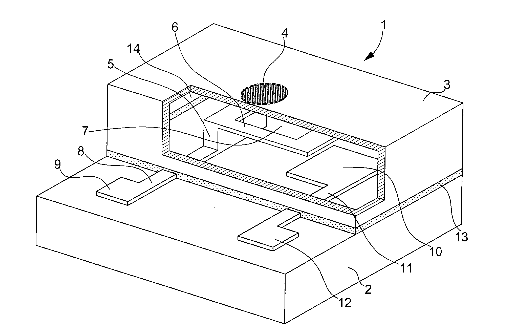
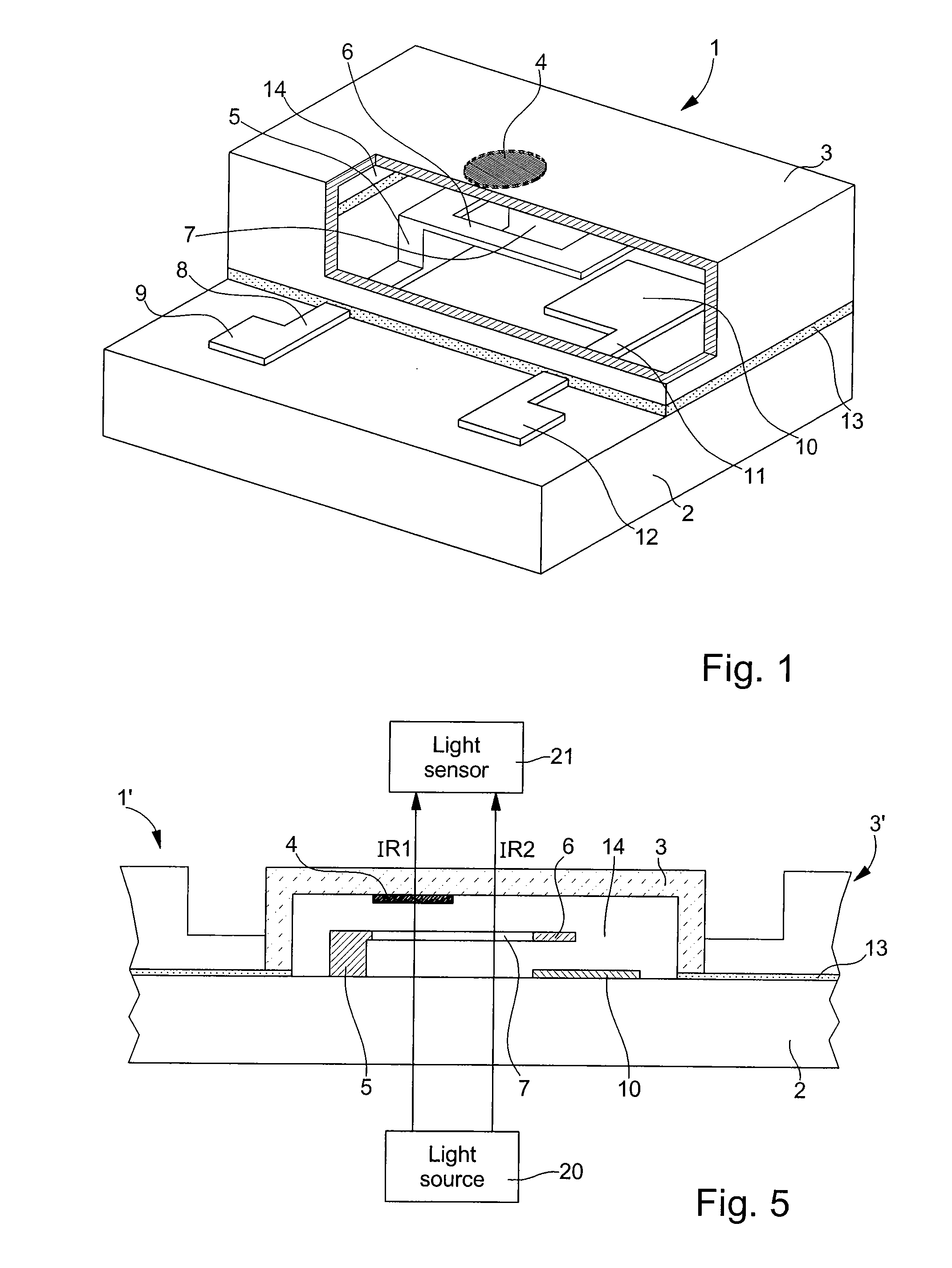
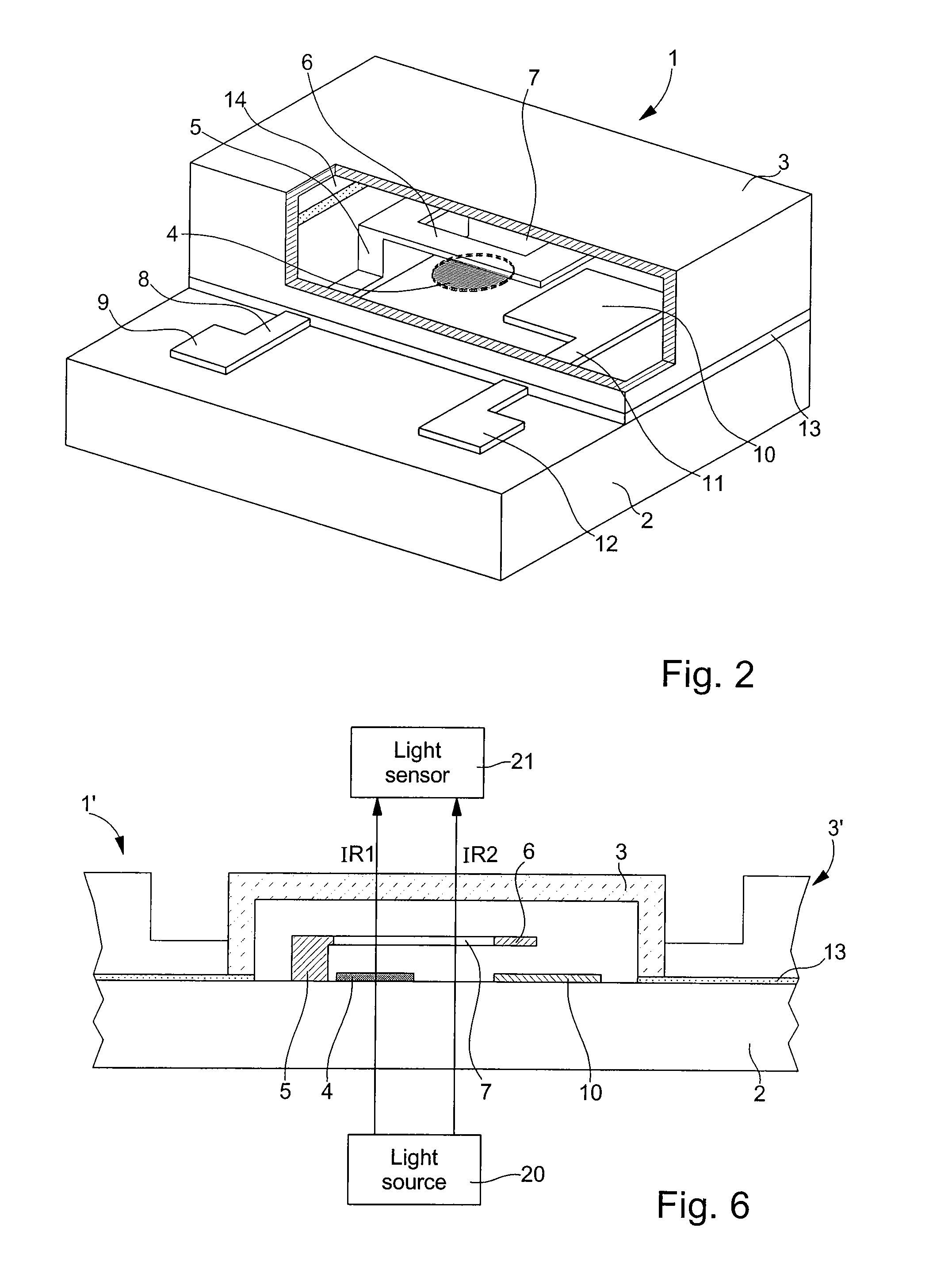
[0039] Micrometric component 1 includes a three-dimensional structure 5, 6 and 10 made over one portion of a substrate 2, a cap 3 for protecting the structure fixed onto a zone of substrate 2 and an indicator element 4 sensitive to a specific reactive fluid. The indicator element 4 is placed on a top part of the inner surface of cap 3 in this A closed cavity 14 is delimited by the inner surface of cap 3, the three-dimensional structure 5, 6 and 10 and the zone of substrate 2.

[0040] The volume of one cavity 14 of such a micrometric component 1 is of the order of 0.02 mm3 (1000 μm long, 200 μm wide and 100 μm high). This cavity 14 with a very small volume is preferably filled with an inert gas, such as argon, at a pressure close to atmospheric pressure.

[0041] The three-dimensional structure 5, 6 and 10 can be a magnetic micro-contactor. For technical details regarding the making of this micro-contactor, the reader can refer to EP Patent No. 0 874 379 by the same Applicant which is c...

second embodiment

[0053] It is possible to make the copper or titanium layer 4 by selective chemical etching or deposition techniques by evaporation under vacuum as explained hereinbefore. It should be noted that chemical etching in this second embodiment can also be used given that the copper layer is made on a flat surface of substrate 2, for example on an insulating layer.

[0054] Since the copper or titanium layers of this second embodiment are made during manufacturing of the wafers on the substrates, the manufacturing time of said wafers may be slower than the manufacturing time of the wafers of the first embodiment of the micrometric components. However, the dimensions of this copper or titanium layer for each cap 3 may be equal to those mentioned in the first embodiment.

[0055] With reference to FIG. 3, a thermal container 30 is shown in a very simplified manner for the explanation of the first steps of the method of checking the hermeticity of several micrometric components. Of course, all of ...

third embodiment

[0078]FIG. 7 shows a micrometric component 1 for implementing the method for checking hermeticity via electric means. It should be noted that those elements of FIG. 7, which are the same as those of FIGS. 1 and 2 bear identical reference signs. Consequently, for the sake of simplification, the description of these elements will not be repeated.

[0079] For checking the hermeticity of cavity 14 of micrometric component 1 via electric means, instead of the copper layer, there is provided a palladium resistor 15 housed entirely in said closed cavity. In order to have a significant resistor value capable of being easily measured by a measuring apparatus, the resistor describes a coil in the cavity. Of course, the length of the coil can be much greater than that illustrated in FIG. 7. This palladium resistor can be made by an electrolytic process, by chemical etching or any other known manner.

[0080] A third conductive path 16 connects a first end of resistor 15 to a third electric contact...


PUM

PropertyMeasurementUnit
pressureaaaaaaaaaa
thicknessaaaaaaaaaa
thicknessaaaaaaaaaa

Abstract

In order to check the hermeticity of a closed cavity of at least one micrometric component, said component includes a structure made over or in one portion of a substrate, a cap fixed to one zone of the substrate to protect the structure, and an indicator element whose optical or electrical properties change in the presence of a reactive fluid. The indicator element may be a copper layer for an optical check or a palladium resistor for an electrical check. The micrometric component is placed in a container which is then hermetically closed. This container is filled with a reactive fluid under pressure, which is oxygen for the optical check and hydrogen for the electrical check. The component in the container is subjected to a reactive fluid pressure higher than 10 bars for a determined time period, and to thermal (T>100° C.) or optical (λ<500 nm) activation. After this time period, an optical or electrical check of the indicator element determines the hermeticity of said cavity.

Description

[0001] This is a National Phase Application in the United States of International Patent Application No. PCT / EP2004 / 012626 filed Nov. 8, 2004, which claims priority on European Patent Application No. 03026780.1, filed Nov. 21, 2003 The entire disclosures of the above patent applications are hereby incorporated by reference.FIELD OF THE INVENTION [0002] The invention concerns a method of checking the hermeticity of a closed cavity of at least one micrometric component. The micrometric component includes a structure made on or in a portion of a substrate and a cap fixed onto one zone of the substrate for protecting the structure. The cavity of the micrometric component is delimited by the inner surface of the cap, the structure and the substrate zone. This cavity can be filled for example with an inert gas at a pressure close to atmospheric pressure or can be a vacuum cavity. [0003] The invention also concerns the micrometric component with a closed cavity for implementing the checkin...

Claims


Application Information

Patent Timeline
Patent Type & Authority Applications(United States)
IPC IPC(8): G01N33/00B81C99/00B81B7/00G01M3/04G01M3/38G01M3/40
CPCB81C99/0045G01M3/40G01M3/38G01M3/047B81B7/00B81C99/00G01M3/04
Inventor GUEISSAZ, FRANCOISRANDIN, JEAN-PAUL
Owner THE SWATCH GRP RES & DEVELONMENT LTD
Why Eureka
Try Eureka