Tear and abrasion resistant expanded material and reinforcement

Inactive Publication Date: 2007-09-06
SCANLON JOHN JAMES +1
View PDF15 Cites 1243 Cited by
  • Summary
  • Abstract
  • Description
  • Claims
  • Application Information

AI Technical Summary

Benefits of technology

[0019] A further object of the present invention is to provide a reinforcement material suitable for stenting that has improved flexibility; a less complex manufacturing process; a wall thickness of varying thickness to reduce stress concentrations at the juncture between the stent and the passageway in which it is installed; and an ability to be easily produced in a large variety of sizes so that less stents are required by procedure.
[0020] It is one mo

Problems solved by technology

Due to the limitations of the materials employed, these prior art grafts have relatively large wall thicknesses that limit the bore size in cylindrical embodiments which results in a restriction or a pressure drop as contents such as blood flow through the graft.
The heavy wall thickness also increases the possibility of the living body rejecting the foreign graft.
Furthermore, the prior art expanded polytetrafluoroethylene materials have inferior physical properties such as strength and abrasion resistance which are important properties for safe installation and providing long service life.
Despite attempts to make stents more flexible through the use of a large variety of configurations, the reinforcements used for stenting made of these prior art materials are sometimes difficult to install in small or curved passageways.
In addition, due to size limitations a surgeon normally needs over two stents on average to complete a stenting procedure.
This stress concentration can result in failure of fragile passageways such as human arteries or veins.
Coated medical devices have experienced problems with the coating flaking off or causing the recipient to have an allergic reaction when in-vivo.
Pathologists have also found that drug eluting metallic stents have problems with delayed healing so that the endothelial layer of cells that would normally cover the members of the stent was non-existent or uneven thereby resulting in thrombosis which resulted in patient death.
This therapy adds substantial daily expense for the patient and in many cases the patients are allergic to the m

Method used


Image

  • Tear and abrasion resistant expanded material and reinforcement
  • Tear and abrasion resistant expanded material and reinforcement
  • Tear and abrasion resistant expanded material and reinforcement

Examples


example 1

Expanded Material Used As Vascular Grafts

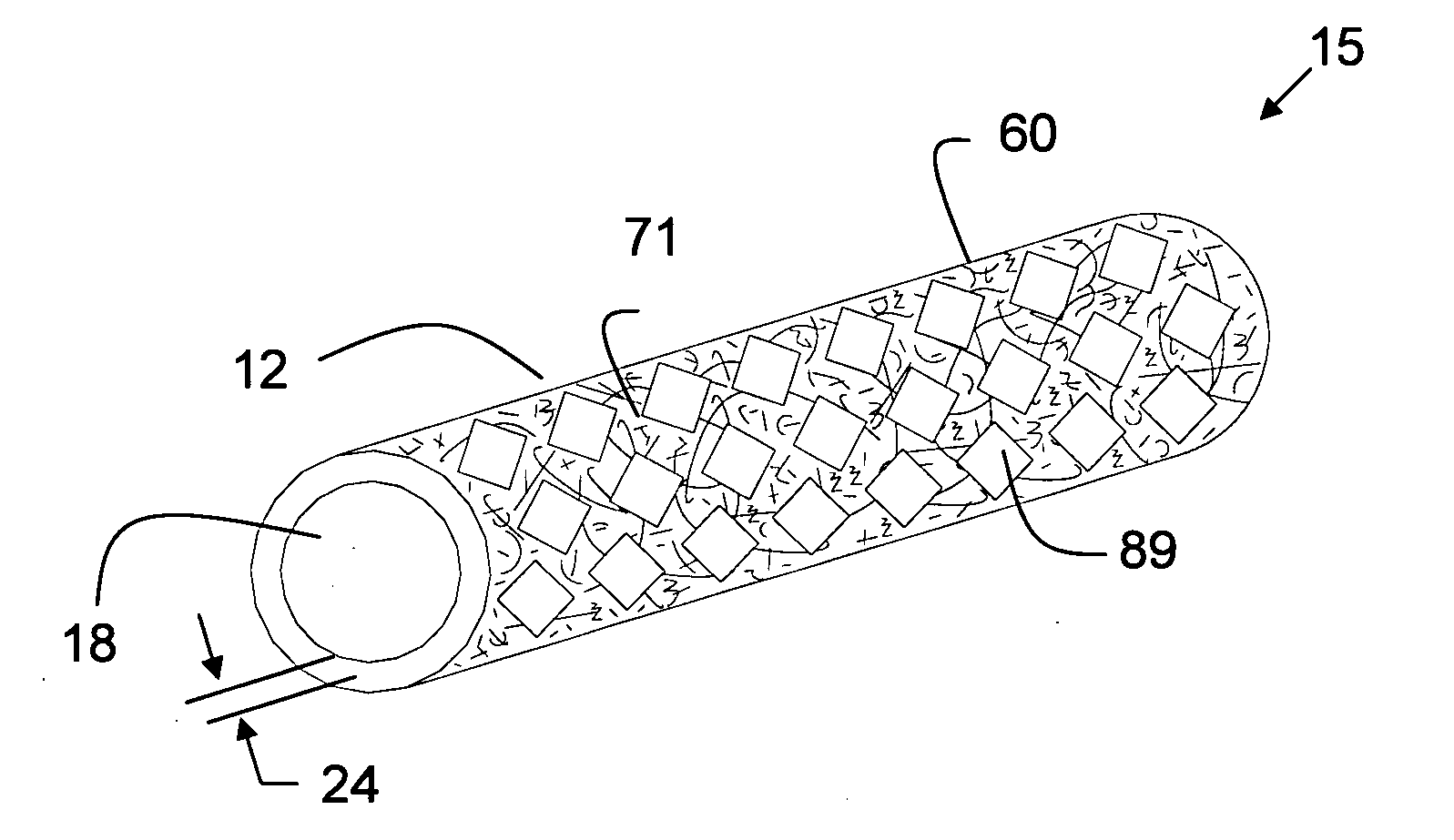
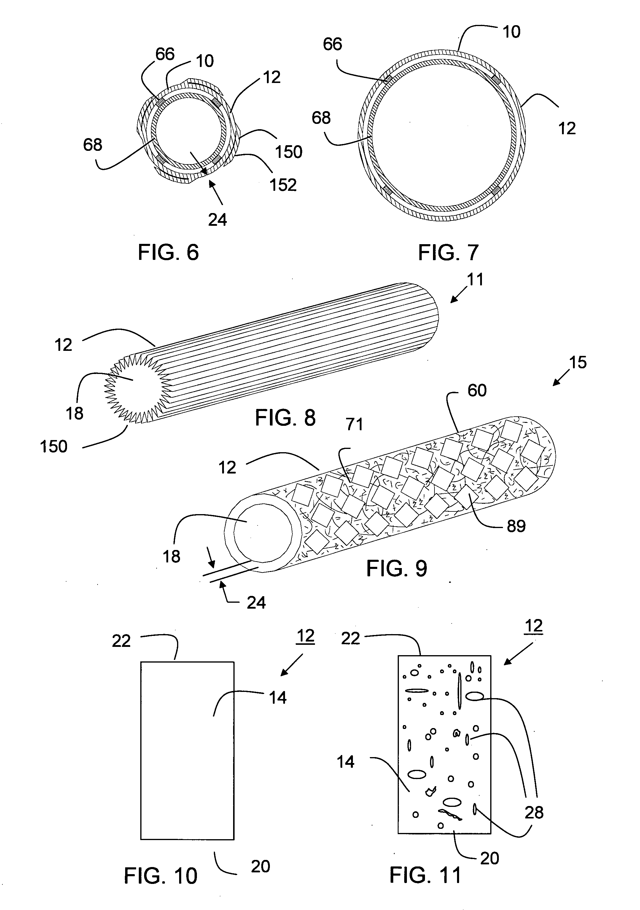
[0304] A thin wall, cylindrical shaped expanded tubular profile having a diameter of approximately 6 mm and a wall thickness of approximately 0.10 mm made of two layers of expanded material comprising polytetrafluoroethylene (PTFE) material having a structure including fibrils and voids that includes a plurality of glass nano fibers and nano size silicon dioxide crystals is converted into a prosthesis for a medical application. The fibrils of the expanded material have a mean length in the range of about 15-25 microns. The prosthesis is used as a coronary artery bypass graft (CABG) in a medical procedure. The prosthesis includes a microencapsulated active ingredient positioned between the two layers of expanded material that is delivered to the patient after installation over a period of 90 days in a descending rate to minimize the rejection of the prosthesis in the human body. Other examples were produced in diameters ranging in size from a...

example 2

Reinforcements of Formable Composite Used In Stenting Procedures

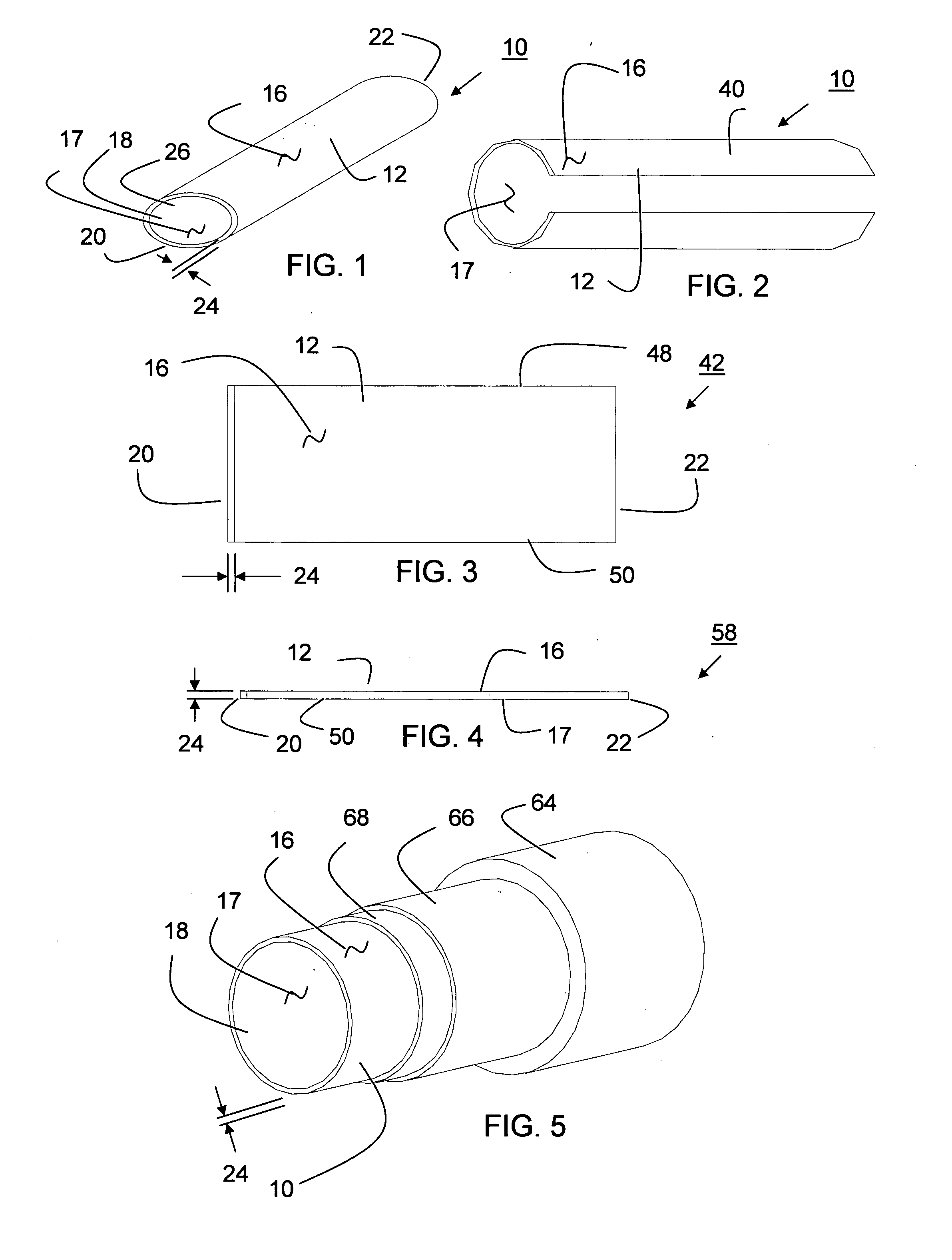
[0305] A cylindrical shaped reinforcement having a diameter of 6 mm is comprised of a wall thickness having a plurality of rectangular shaped open cells surrounded by member segments having a rectangular cross section. The member segments having a thickness of about 0.0762 mm (0.003 inches) near the first and second ends and about 0.127 mm (0.005 inches) near middle are made of a formable composite including a plurality of deformable elements encapsulated in a binder of polytetrafluoroethylene (PTFE). Samples are produced using discontinuous deformable elements made of stainless steel and Nitinol®. Samples are produced wherein the deformable elements range in size from 10 to 500% the length of the member segments. Samples are produced wherein the ratio of first size to second size ranges from about 1:2 to 1:10. Other samples are prepared for neurological applications having a diameter of about 2 mm and larger sizes lik...

example 3

Expanded Material and Reinforcement Used as Stent-Graft

[0308] The expanded materials of Example 1 are combined with the reinforcements of Example 2 to produce stent-grafts. The stent-grafts are surgically implanted in a human body blood carrying passageway to repair an aneurismal vessel.


PUM

PropertyMeasurementUnit
Lengthaaaaaaaaaa
Thicknessaaaaaaaaaa
Thicknessaaaaaaaaaa

Abstract

The present invention is a more durable expanded material that enables thinner wall thicknesses and a more flexible reinforcement suitable for stenting. The present invention is especially useful in the construction of grafts, stents, and stent-grafts which are used, for example, in repairing or replacing blood vessels that are narrowed or occluded by disease, aneurismal blood vessels, or other medical treatments. The inventive material and configurations allow expansion or contraction in size or adjustment in size in an incremental manner so that the optimum size, shape, and fit with other objects can be obtained. The present invention is also optionally capable of more accurately delivering one or more active ingredients such as drugs over longer periods of time. The present invention optionally includes surface modifications and additives that increase the surface adhesion of active ingredients, coatings, or combinations thereof. Finally, the present invention optionally includes growing cells on the inventive material so that the expanded material, reinforcement, or combinations thereof are useful, for example, in producing lab-grown blood vessels or organs.

Description

RELATED APPLICATION [0001] This application claims benefit of Provisional Patent Application Ser. No. 60 / 779,128 filed 04 Mar. 2006.FIELD OF INVENTION [0002] The present invention relates to improved materials and configurations for use in the manufacturing of medical devices such as expandable intraluminal stents, grafts, stent-grafts, surgical fabrics, suppositories, transdermal patches, or oral medications that optionally deliver active ingredients within a living body. BACKGROUND OF INVENTION [0003] The prior art describes a variety of grafts that are used for the replacement of diseased passageways in a living body. In addition, the prior art teaches several metallic reinforcements used for stenting to hold open constricted passageways in a living body. Moreover, there exists in the prior art stent-grafts which are generally a combination of these two separate components which are commonly used to repair aneurismal vessels. [0004] The prior art includes grafts manufactured of m...

Claims


Application Information

Patent Timeline
IPC IPC(8): A61F2/06A61F2/94
CPCA61F2/07A61F2220/0075A61F2/915A61F2002/072A61F2002/91533A61F2002/9155A61F2002/91558A61F2250/0068A61K47/48992A61L31/048A61L31/10A61L31/146A61L31/16A61L2300/00B23K26/4065A61F2/91A61F2220/0058A61F2/90A61F2002/075B29C55/26A61F2210/0076A61F2220/0008A61F2220/0025A61F2220/0041A61F2220/005C08L27/18A61K47/6957B23K2103/42B23K2103/50
Inventor SCANLON, JOHN JAMESSCANLON, CATHERINE ANN
Owner SCANLON JOHN JAMES
Why Eureka
Try Eureka