Self-Cleaning Catalytic Chemical Vapor Deposition Apparatus And Cleaning Method Thereof
a catalytic chemical vapor deposition and self-cleaning technology, which is applied in the direction of chemistry apparatus and processes, cleaning using liquids, coatings, etc., can solve the problems of limited use capacity and the deformation and achieve the effect of reducing cost, stable and good film, and suppressing the corrosion-induced degradation of the catalytic body
- Summary
- Abstract
- Description
- Claims
- Application Information
AI Technical Summary
Benefits of technology
Problems solved by technology
Method used
Image

Examples
embodiment 1
[0050] First, Embodiment 1 will be described.
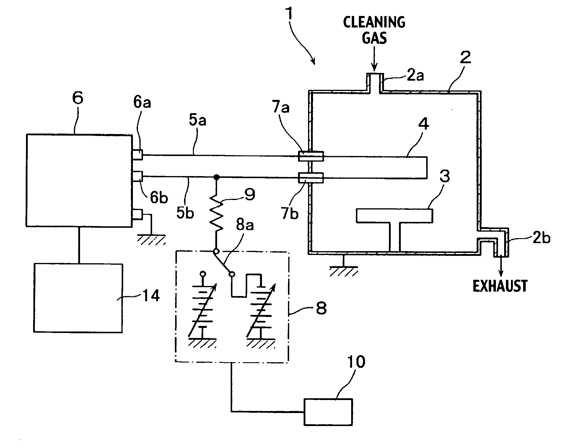
[0051]FIG. 1 is a schematic block diagram showing a self-cleaning catalytic chemical vapor deposition apparatus related to Embodiment 1 of the present invention.
[0052] This self-cleaning catalytic chemical vapor deposition apparatus 1 is provided with a reaction chamber 2, a substrate stage 3 which is provided within this reaction chamber 2 and on which a substrate (not shown) is to be placed, and a catalytic body 4 which is formed from a tungsten wire having a diameter of 0.5 mm, which has the catalytic action to decompose a raw material gas supplied into the reaction chamber 2 by heating the raw material gas.
[0053] The catalytic body 4 decomposes a cleaning gas supplied into the reaction chamber 2 by heating the cleaning gas during cleaning and generates a radical species by the contact of the clean gas with the catalytic body 4.
[0054] As the catalytic body having such a catalytic action, it is possible to use indium, molybdenum, ta...
embodiment 2
[0106] Next, Embodiment 2 will be described.
[0107] In this embodiment, the self-cleaning catalytic chemical vapor deposition apparatus 1 shown in FIG. 1 is used and a zero bias voltage is applied without applying a bias voltage from the constant-voltage power supply 8 to the voltage generated across the terminals of the heating power supply 6.
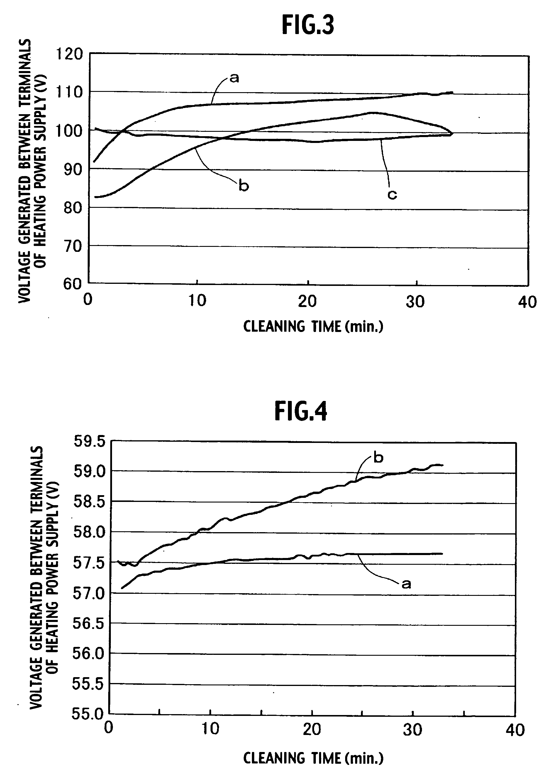
[0108] The cleaning conditions in this embodiment are as follows. The pressure in the reaction chamber is 10 Pa, the wire diameter of the catalytic body is 0.7 mm, and the heating temperature of the catalytic body is 1700° C. As the cleaning gas, a mixed gas of NF3 and H2 was introduced each at a flow rate of 20 sccm.
[0109]FIG. 4 is a diagram which shows the relationship between the voltage generated between terminals of the heating power supply indicative of the occurrence of etching of the catalytic body itself and the cleaning time of Embodiment 2. The character a denotes a case where a mixed gas of NF3 and H2 is used as the cleaning gas ...
embodiment 3
[0118] Next, Embodiment 3 will be described.
[0119]FIG. 5 is a schematic block diagram showing the self-cleaning catalytic chemical vapor deposition apparatus related to Embodiment 3.
[0120] Incidentally, like reference numerals refer to members having the same function as the self-cleaning catalytic chemical vapor deposition apparatus shown in FIG. 1 and overlapping descriptions of these members are omitted.
[0121] This self-cleaning catalytic chemical vapor deposition apparatus 20 is provided, on the outer side of the reaction chamber 2, with a vessel for cleaning gas decomposition 11 as a radical generator which decomposes a cleaning gas and generates a radical species.
[0122] The vessel for cleaning gas decomposition 11 is provided with a plasma generator 12 of RF plasma, microwave plasma and the like, and can generate halogen-containing radical species by the plasma decomposition of an introduced clean gas, for example, a mixed gas of NF3 and Ar by electromagnetic energy.
[0123...
PUM
| Property | Measurement | Unit |
|---|---|---|
| Temperature | aaaaa | aaaaa |
| Polarity | aaaaa | aaaaa |
| Electrical resistance | aaaaa | aaaaa |
Abstract
Description
Claims
Application Information
 - R&D
- Intellectual Property
- Life Sciences
- Materials
- Tech Scout
- Unparalleled Data Quality
- Higher Quality Content
- 60% Fewer Hallucinations
Browse by: Latest US Patents, China's latest patents, Technical Efficacy Thesaurus, Application Domain, Technology Topic, Popular Technical Reports.
© 2025 PatSnap. All rights reserved.Legal|Privacy policy|Modern Slavery Act Transparency Statement|Sitemap|About US| Contact US: help@patsnap.com