
Magnetic recording medium, method of manufacturing the same, and magnetic recording apparatus

a technology of magnetic recording medium and magnetic recording medium, which is applied in the field of magnetic recording medium, a method of manufacturing magnetic recording medium, and a magnetic recording apparatus, can solve the problems of difficult to achieve magnetic wall in these materials, and achieve the effects of improving mechanical strength and hdi (head disk interface) characteristics, suppressing magnetic leakage flux, and improving film quality of protective layer

Inactive Publication Date: 2007-09-20
SHOWA DENKO KK
View PDF4 Cites 52 Cited by
  • Summary
  • Abstract
  • Description
  • Claims
  • Application Information

AI Technical Summary

Benefits of technology

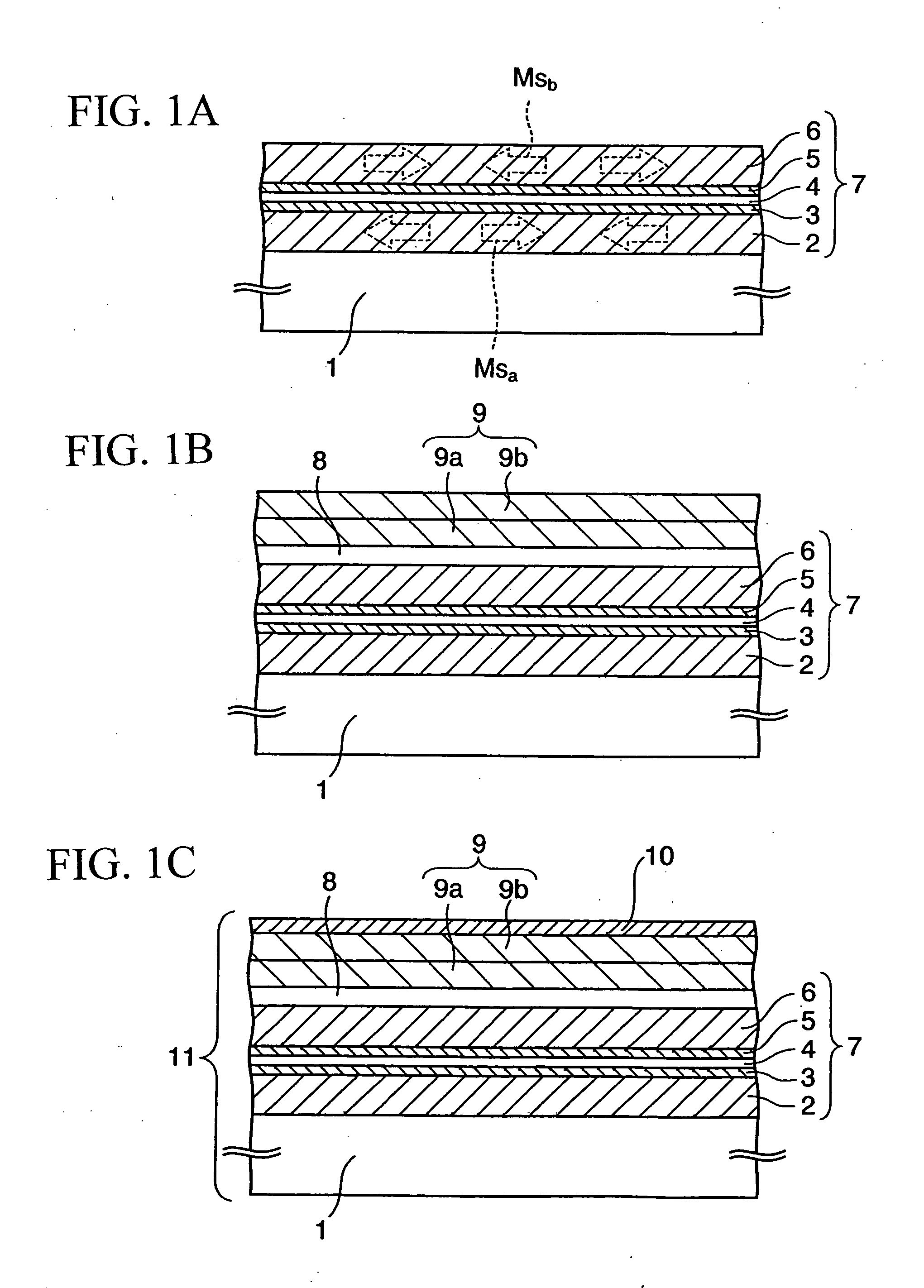
[0020] According to the present invention, the crystalline magnetic layer whose interface with the non-magnetic layer is stabile is formed, thereby suppressing the diffusion of the constituent material of the non-magnetic layer into the lower soft magnetic underlying layer or into the upper soft magnetic underlying layer due to an aged deterioration or the like. Accordingly, the lower soft magnetic underlying layer and the upper soft magnetic underlying layer are distinctly separated by the non-magnetic layer, so that these soft magnetic underlying layers anti-ferromagnetically couple to each other excellently. Consequently, a magnetic leakage flux which leaks from each underlying layer to the outside of the magnetic recording medium can be reduced, so that the spike noise due to the magnetic leakage flux can be suppressed effectively.
[0022] It should be noted, however, that other elements can easily diffuse into the film made of the amorphous or the microcrystalline material, since the structure of these materials is in a quasi-stable state. Despite using the amorphous or the microcrystalline material as the soft magnetic underlying layer, constituent material of the non-magnetic layer is prevented from diffusing into the soft magnetic underlying layer by the crystalline magnetic layer in the present invention. Therefore, even when the amorphous or the microcrystalline material is employed as the soft magnetic layer, increase of the spike noise due to the diffusion of the materials can be suppressed, while suppressing the generation of the magnetic wall by the nature of the amorphous or the microcrystalline material in the present invention.
[0024] In the present invention, by heating the base member in the step of forming the protective layer, the protective layer is densified to improve its mechanical strength and an HDI (Head Disk Interface) characteristic. Because the diffusion of the constituent material of the non-magnetic layer into the soft magnetic underlying layers is prevented by the crystalline magnetic layer even if the base member is heated this manner, simultaneous pursuit of improvement in the film quality of the protective layer and the suppression of the magnetic leakage flux can be achieved.

Problems solved by technology

In particular, since an amorphous material and a microcrystalline material does not have a distinct magnetic domain structure, the magnetic wall is difficult to occur in these materials.

Method used


Image

  • Magnetic recording medium, method of manufacturing the same, and magnetic recording apparatus
  • Magnetic recording medium, method of manufacturing the same, and magnetic recording apparatus
  • Magnetic recording medium, method of manufacturing the same, and magnetic recording apparatus

Examples


first embodiment

(1) First Embodiment

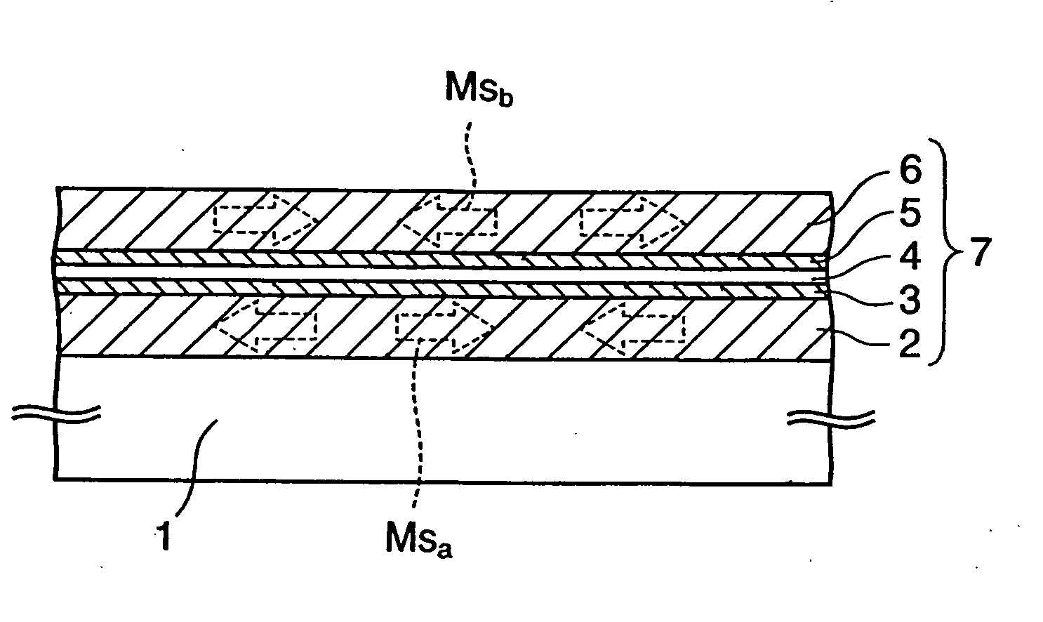
[0038]FIGS. 1A to 1C are cross sectional views in the course of manufacturing a magnetic recording medium according to the present embodiment.

[0039] First, the steps until obtaining the sectional structure shown in FIG. 1A are described.

[0040] First, CoNbZr layer is formed as a lower soft magnetic underlying layer 2 to a thickness of about 20 to 24 nm on a non-magnetic base member 1 that is manufactured by applying an NiP plating to the surface of an Al alloy base member or a chemically strengthened glass base member. CoNbZr layer for the lower soft magnetic underlying layer 2 is an amorphous material, and is formed by a DC sputtering method with an input electric power of 1 kW in an Ar atmosphere of the pressure of 0.5 Pa.

[0041] Note that, a crystallized glass, or a silicon substrate in which a thermal oxidation layer is formed on the surface thereof may be used as the non-magnetic base member 1. Furthermore, the lower soft magnetic underlying layer 2 is not ...

second embodiment

(2) Second Embodiment

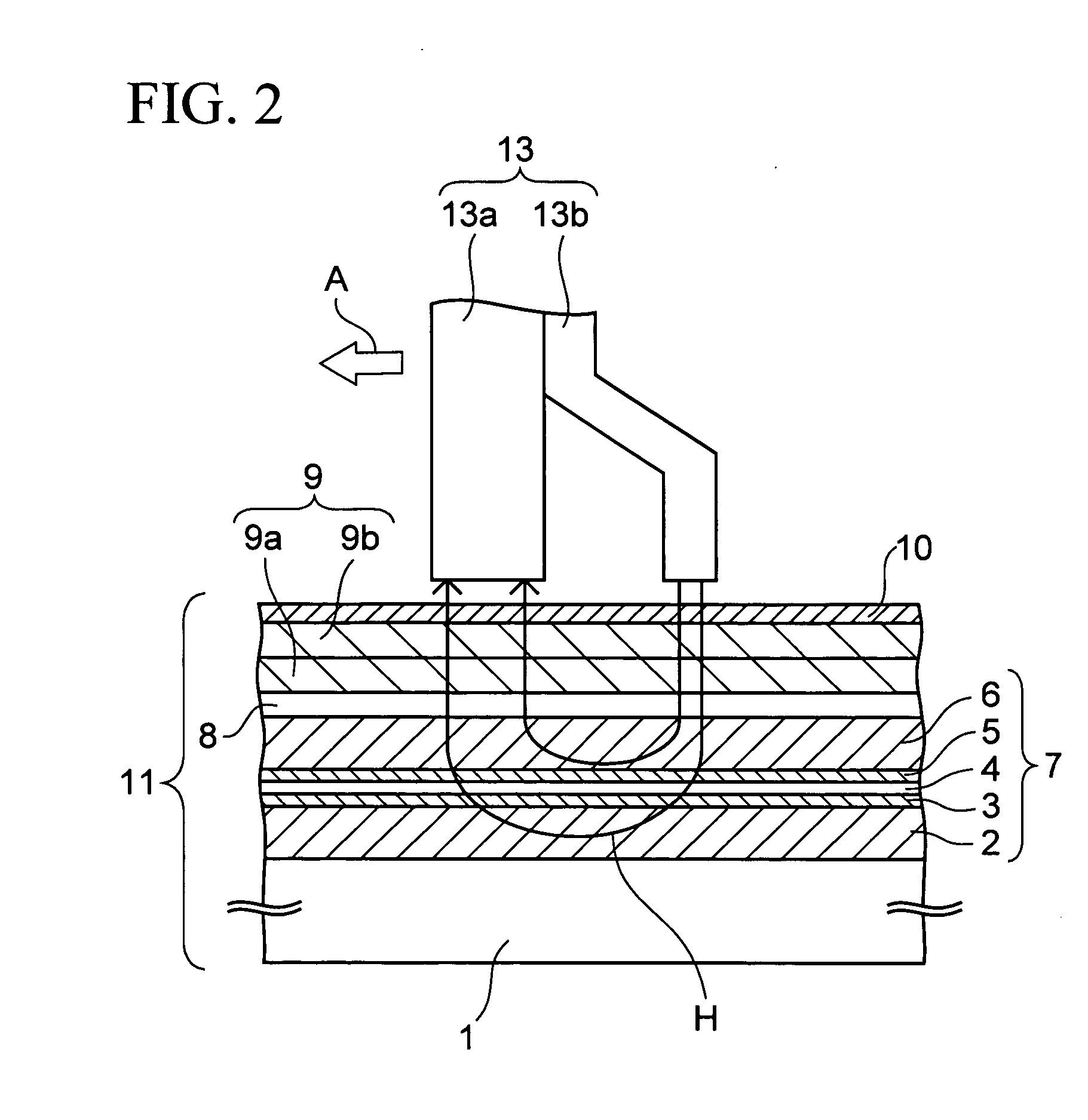
[0110] In this embodiment, a magnetic recording apparatus comprising the above-described magnetic recording medium 11 of the first embodiment is described.

[0111]FIG. 11 is a plane view of the magnetic recording apparatus. This magnetic recording apparatus is a hard disk drive unit to be installed in a personal computer, or in a video-recording apparatus of a television.

[0112] In this magnetic recording apparatus, by means of a spindle motor or the like, the magnetic recording medium 11 is rotatably mounted in a housing 17 as a hard disk. Furthermore, a carriage arm 14 is provided in the housing 17, which is rotatable about an axis 16 by means of an actuator or the like. A magnetic head 13 is provided at the tip of the carriage arm 14. The magnetic head 13 scans the magnetic recording medium 11 from the above, thereby carrying out writing and reading of magnetic information to and from the magnetic recording medium 11.

[0113] It should be noted that the type of...


PUM

PropertyMeasurementUnit
thicknessaaaaaaaaaa
thicknessaaaaaaaaaa
thicknessaaaaaaaaaa

Abstract

According to the present invention, provided is a magnetic recording medium 11 comprising: a non-magnetism base member 1; a lower soft magnetic underlying layer 2 formed on the non-magnetism base member 1; a non-magnetic layer 4 formed on the lower soft magnetic underlying layer 2; an upper soft magnetic underlying layer 6 formed on the non-magnetic layer 4; and a recording layer 9 having a perpendicular magnetic anisotropy, the recording layer 9 being formed on the upper soft magnetic underlying layer 6, wherein crystalline magnetic layers 3 and 5 are formed between the lower soft magnetic underlying layer 2 and the non-magnetic layer 4 or between this non-magnetic layer 4 and the upper soft magnetic underlying layer 6.

Description

CROSS-REFERENCE TO RELATED APPLICATIONS [0001] This application is based on and claims priority of Japanese Patent Application No. 2006-072924 filed on Mar. 16, 2006, the entire contents of which are incorporated herein by reference. BACKGROUND OF THE INVENTION [0002] 1. Field of the Invention [0003] The present invention relates to a magnetic recording medium, a method of manufacturing magnetic recording medium, and a magnetic recording apparatus. [0004] 2. Description of the Related Art [0005] In recent years, in magnetic storage apparatuses such as a hard disk drive unit, increase in the storage capacity has been remarkable, and the surface recording density of the magnetic recording medium incorporated in the apparatus has been steadily increasing. Those used as such a magnetic recording medium for many years include an in-plane recording medium, in which the direction of magnetization recorded in a recording layer is in the in-plane direction. However, in the in-plane magnetic ...

Claims


Application Information

Patent Timeline
Patent Type & Authority Applications(United States)
IPC IPC(8): G11B5/82
CPCG11B5/66G11B5/82G11B5/667G11B5/672G11B5/676G11B5/84G11B2005/0029Y10S428/90
Inventor INAMURA, RYOSAKUKAITSU, ISATAKE
Owner SHOWA DENKO KK
Learn More