Magnetic recording medium and a method of manufacturing the same

a technology of magnetic recording media and manufacturing methods, which is applied in the field of magnetic recording media, can solve the problems of significant degradation of signal quality, form and arrange dots, and difficulty in regularly arranging dots in circumferential and radial directions. achieve the effect of high density recording

Inactive Publication Date: 2007-09-20
FUJI ELECTRIC CO LTD
View PDF13 Cites 20 Cited by
  • Summary
  • Abstract
  • Description
  • Claims
  • Application Information

AI Technical Summary

Benefits of technology

[0021]The dots are magnetically isolated from each other because the dots are separated by the additive of the nonmagnetic substance. Plural dots of magnetic particles can grow on one crystal grain of the ruthenium underlayer, or one dot of magnetic particle can grow over plural grains of ruthenium underlayer. The size and distance of the magnetic dots on the ridge line can be changed by changing an amount of additives in the magnetic component, deposition conditions of the magnetic recording layer, and annealing conditions after the deposition corresponding to the line pitch of the undulating structure. The processes of deposition and heating are similar to those used in manufacturing conventional magnetic recording media, and simple processes.
[0022]The method of the invention does not include any step of machining or processing a magnetic recording layer for forming the magnetic dots. Consequently, the magnetic properties of the dots are not degraded by the damage due to such processing. When the difference in height between the top and bottom lines of the undulating structure is controlled in the range from less than 1 nm to several nm, a planarization treatment such as polishing is not needed, and coverage with the protective layer is secured, and thus no problem of corrosion is caused. Flying performance is also good in employing a flying magnetic head that is used in normal magnetic recording systems. Processing of the undulating structure can be simplified by employing direct patterning by EB, which does not include steps of coating and removal of resist. Batch patterning on a large area can be carried out as well by employing a stamp technique of a master disk.
[0025]Such a magnetic recording medium of the invention can be manufactured by a simple process in which an undulating structure is formed on the surface of the ruthenium underlayer and a magnetic recording layer is deposited on this surface.

Problems solved by technology

However, since one bit is made up of a plurality of grains, “transition noise” due to a zigzag configuration between the bits along the grains causes a significant problem of degradation in signal quality.
This problem is common in both longitudinal and perpendicular systems, and is a critical factor that limits recording density in the perpendicular magnetic recording system.
All the patterned media having regularly arranged dots as mentioned above involve a serious problem in the manufacturing process thereof.
The problem is how to form and arrange the dots in a simple process.
In a disk substrate as practically employed at present, it is very difficult to regularly arrange the dots in circumferential and radial directions.
It is possible to make a dot pattern using a semiconductor process as described above, however, it requires a tremendous processing time.
Moreover, it is very difficult to form every fine dot having a dot size less than 30 nm, for example, with sufficient accuracy.
Processing of a magnetic film raises a problem of degradation of magnetic property due to thermal damage.
Formation of nanoholes at the present state of the art presents difficulty in compatibility between minimization and regular arrangement.
In addition, the process is complicated because a planarizing treatment of the surface is needed after filling the holes with magnetic material.
As described thus far, the proposed techniques of dot formation in the patterned medium are complicated and involve various problems in manufacturing the patterned medium.

Method used


Image

  • Magnetic recording medium and a method of manufacturing the same
  • Magnetic recording medium and a method of manufacturing the same
  • Magnetic recording medium and a method of manufacturing the same

Examples


example 1

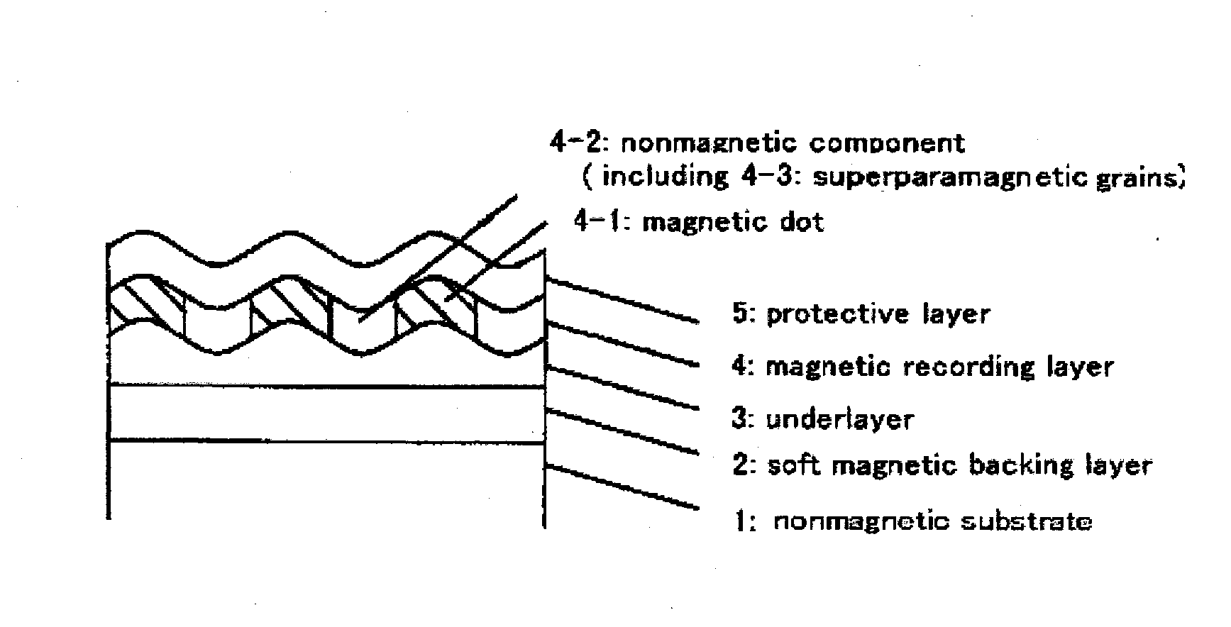
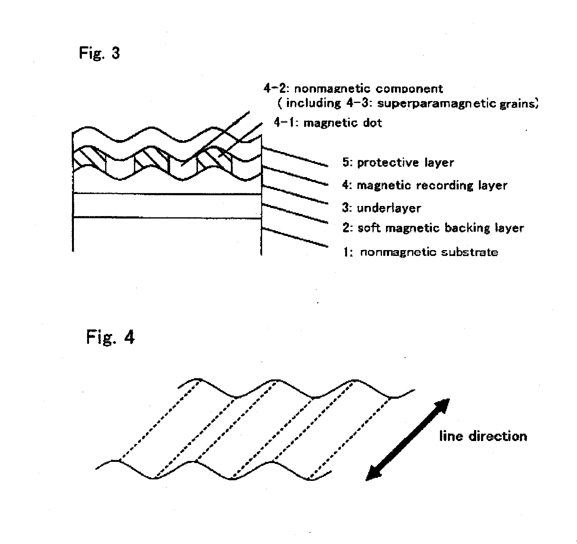
[0049]Nonmagnetic substrate 1 was a silicon substrate in a disk shape with a smooth surface of a surface roughness Ra=0.5 nm. After cleaning, the substrate was introduced into an EB apparatus and line processing was conducted on the substrate surface. The processing was carried out fixing the position of the electron beam and moving the substrate horizontally in the radial direction while rotating the substrate to make concentric circles. The distance between the ridge lines was controlled to 25 nm and the difference in height between top and bottom lines of the undulating structure was controlled to 10 nm. Then, the substrate was introduced into a sputtering apparatus and soft magnetic backing layer 2 of amorphous CoZrTa was formed to a thickness of 100 nm using a target of Co92Zr5Ta3 under an argon gas pressure of 5 mTorr. Subsequently, ruthenium underlayer 3 having a thickness of 5 nm was deposited using a ruthenium target under an argon gas pressure of 3 mTorr. Then, magnetic re...

example 2

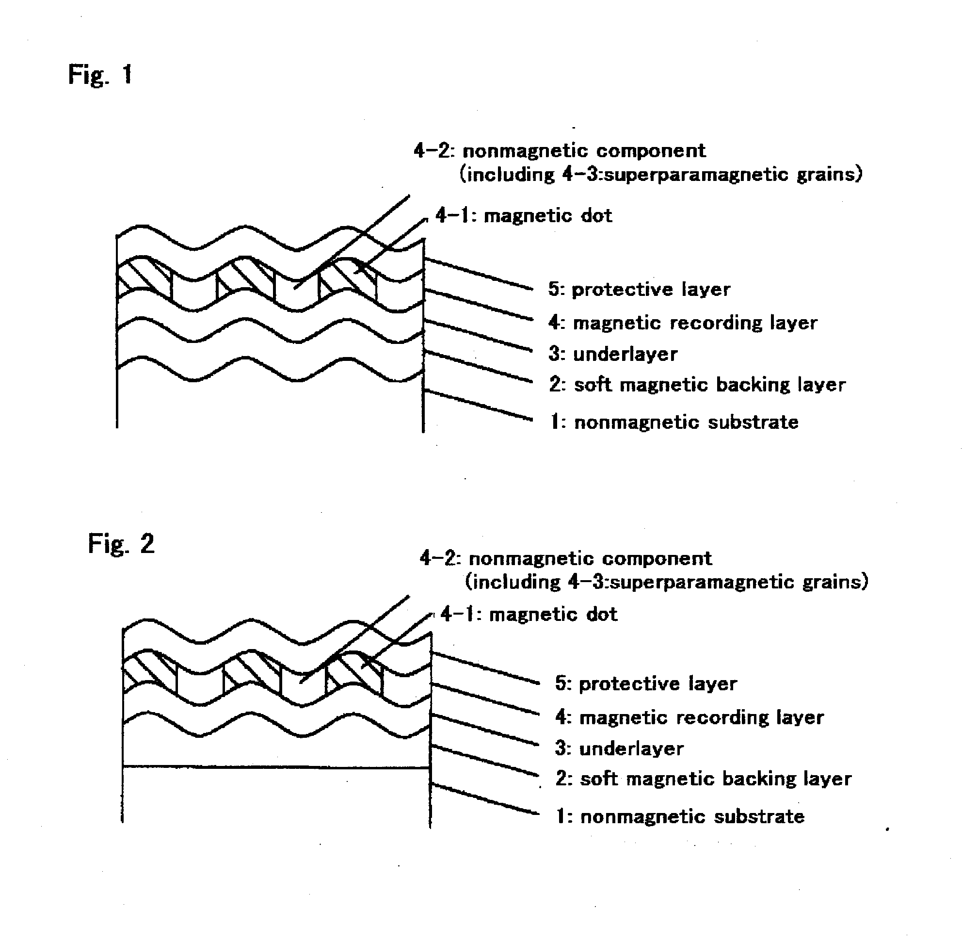
[0050]Nonmagnetic substrate 1 used was the same as that in Example 1. After cleaning, the substrate was introduced into a sputtering apparatus and soft magnetic backing layer 2 of CoZrTa having a thickness of 100 nm was formed in the same manner as in Example 1. Introducing the substrate into an EB apparatus, a line processing was conducted on the surface of soft magnetic backing layer 2. Concentric circles were formed in the line processing in the same manner as in Example 1. The distance between the ridge lines was controlled to 25 nm and the difference in height between top and bottom lines of the undulating structure was controlled to 3 nm. After that, ruthenium underlayer 3, magnetic recording layer 4 of CoPt—SiO2, carbon protective layer 5, and a liquid lubricant layer were sequentially formed in the same manner as in Example 1. Thus, a magnetic recording layer of Example 2 was manufactured.

example 3

[0051]Nonmagnetic substrate 1 used was the same as that in Example 1. After cleaning, the substrate was introduced into a sputtering apparatus and soft magnetic backing layer 2 of CoZrTa having a thickness of 100 nm and ruthenium underlayer 3 having a thickness of 5 nm were formed in the same manner as in Example 1. Introducing the substrate into an EB apparatus, a line processing was conducted on the surface of ruthenium underlayer 3. Concentric circles were formed in the line processing in the same manner as in Example 1. The distance between the ridge lines was controlled to 25 nm and the difference in height between top and bottom lines of the undulating structure was controlled to 3 nm. After that, magnetic recording layer 4, protective layer 5, and a liquid lubricant layer were sequentially formed in the same manner as in Example 1. Thus, a magnetic recording layer of Example 3 was manufactured.


PUM

PropertyMeasurementUnit
grain sizeaaaaaaaaaa
grain boundary widthaaaaaaaaaa
sizeaaaaaaaaaa

Abstract

A magnetic recording medium having magnetic dots that can achieve high density recording is disclosed. The magnetic recording medium comprises at least an underlayer, a magnetic recording layer, and a protective layer sequentially laminated on a nonmagnetic substrate. The underlayer is composed of ruthenium or an alloy of mainly ruthenium and has an undulating structure formed with ridge lines in a predetermined pitch on the surface of the underlayer. The magnetic recording layer contains at least ferromagnetic crystal grains and a nonmagnetic component. Magnetic dots composed of crystal grains with a grain size not smaller than 4 nm in the magnetic recording layer are aligned on a surface of the underlayer along the ridge line, and each of the magnetic dots s separated by the nonmagnetic component from each other. A simple manufacturing method for this medium also is disclosed.

Description

CROSS REFERENCE TO RELATED APPLICATIONS[0001]This application is based on, and claims priority to, Japanese Patent Application No. 2006-070492, filed on Mar. 15, 2006, the contents of which are incorporated herein by reference in their entirety.BACKGROUND OF THE INVENTION[0002]A. Field of the Invention[0003]The present invention relates to magnetic recording media installed in various magnetic recording devices, and to a method of manufacturing the media.[0004]B. Description of the Related Art[0005]Recently, “a perpendicular magnetic recording system” has been applied in practical use in place of conventional “longitudinal magnetic recording system” for enhancing the magnetic recording density. The recording magnetization is perpendicular to the medium surface in the perpendicular magnetic recording system. A perpendicular magnetic recording medium (hereinafter also simply referred to as “a perpendicular medium”) is mainly composed of a magnetic recording layer of a hard magnetic ma...

Claims


Application Information

Patent Timeline
Patent Type & Authority Applications(United States)
IPC IPC(8): G11B5/66B05D5/12
CPCG11B5/667G11B5/855G11B5/7325B05D5/12G11B5/743G11B5/7368G11B5/7377
Inventor WATANABE, SADAYUKI
Owner FUJI ELECTRIC CO LTD
Why Eureka
Try Eureka