
Toner and method of manufacturing the same

a technology of toner and halftone, applied in the field of toner, can solve the problems of deterioration of the fixing property of such a toner in the halftone portion formed thereof, easy high temperature offset phenomena, and relatively large problems of high-speed fixing about toner, and achieve good low-temperature fixing properties, excellent fluidity, and reduced size

Inactive Publication Date: 2007-09-20
RICOH KK
View PDF12 Cites 41 Cited by
  • Summary
  • Abstract
  • Description
  • Claims
  • Application Information

AI Technical Summary

Benefits of technology

[0018] Because of these reasons, the present inventors recognize that a need exists for a toner having an irregular shape and a good low temperature fixing property to produce quality images with high definition regardless of cleaning systems, including a blade cleaning system, while keeping advantageous points as a chemical toner, for example, a narrow particle size distribution, reduction in size and excellent fluidity and also for a method of manufacturing the toner.

Problems solved by technology

High speed fixing involves relatively large problems about toner.
However, when a toner having such a low viscosity is used for a low speed fixing, offset phenomena easily occur at a high temperature.
However, the fixing property of such a toner in a halftone portion formed thereof deteriorates.
Thus, offset phenomenon easily occurs, resulting in poor quality of a resultant fixing image.
When toner is granulated in an aqueous medium, pigments in oil phase having a small droplet form agglomerate at the interface between the oil phase and the aqueous phase, which causes decrease in volume resistance and non-uniform dispersion of the pigments.
Thus, the obtained toner has basic performance problems.
Without targeted forms and characteristics, it is difficult to obtain oilless toner having a small particle diameter with suitably controlled forms and apply the toner to an apparatus.
Each JOP does not include descriptions of methods of making irregular formed toner, which leaves the problems about blade cleaning unsolved.
In this case, polymer design and particle surface design are key to obtain desired charging characteristics and fixing characteristics but there is no specific method of achieving a good fixing performance.
However, a charge controlling agent is fixed on the surface of the toner particle to secure the charging performance, which has an adverse impact on fixing property.
However, generally, particles manufactured from oil phase containing a solvent tend to be spherical so that it is extremely difficult to form a particle having an irregular shape.
However, the spherical toner described in JOPs 2002-148863, H05-313416 and H02-148046 tends to roll on an image bearing member so that the toner easily slips into between the image bearing member and a cleaning blade when a blade cleaning system is adopted, resulting in poor cleaning performance.
In addition, this easily causes a problem that dust gathers around toner dots in the developing process and the transfer process.
However, such a toner is selective in light of a cleaning system.
However, spherical toner rolls between an image bearing member and a cleaning blade and slips into therebetween.
This is a large problem for a cleaning blade system.
However, there is no description for making toner particles have an irregular form so that the toner particles tend to be spherical.
However, this toner is made of styrene-acryl materials so that there is a limit to improving the fixing property of the toner.

Method used


Image

  • Toner and method of manufacturing the same
  • Toner and method of manufacturing the same
  • Toner and method of manufacturing the same

Examples


example 1

Synthesis of Emulsion of Organic Particulates

manufacturing example 1

[0224] The following recipe is placed in a reaction container equipped with a stirrer and a thermometer and the mixture is agitated for 15 minutes at a revolution of 400 rpm to obtain a white emulsion.

Water780partsSodium salt of sulfate of an adduct of methacrylic acid with11partsethyleneoxide (EREMINOR RS-30 manufactured by SanyoChemical Industries Ltd.)Styrene90partsMethacrylic acid90partsButyl acrylate120partsAmmonium persulfate1part

[0225] The emulsion is heated at 75° C. to conduct a reaction for 5 hours. Then, 30 parts of a 1% aqueous solution of ammonium persulfate are added to the emulsion and the mixture is further aged for 5 hours at 75° C. Thus, an aqueous liquid dispersion (Particulate liquid dispersion 1) of a vinyl based cross-linking resin (i.e., a copolymer of styrene, methacrylic acid, and butyl acrylate) is obtained. The volume average particle diameter of Particulate liquid dispersion 1 is 50 nm when measured by LA-920.

[0226] Particulate liquid dispersion 2 is p...

manufacturing example 3

[0232] Eighty five (85) parts of a binder resin (polyester resin: formed of adduct of Bisphenol A with propylene oxide succinic acid derivative, manufactured by Sanyo Chemical Industries Ltd., acid value: 10, Tg: 52° C.) is mixed and kneaded for 15 minutes by a two-roll with a setting of the roll surface temperature of 110° C. and the roll gap of 2 mm. Then, 10 parts of modified montmorillonite (Clayton APA, manufactured by Wilbur-Ellis Co., Ltd.) are placed into the polyester resin, kneaded for 30 minutes and cooled down to room temperature. The resultant is pulverized by a pulverizer to a size of 2 mm φ to obtain Modified laminar inorganic mineral dispersion body 2.

Preparation of Aqueous Phase


PUM

PropertyMeasurementUnit
Temperatureaaaaaaaaaa

Abstract

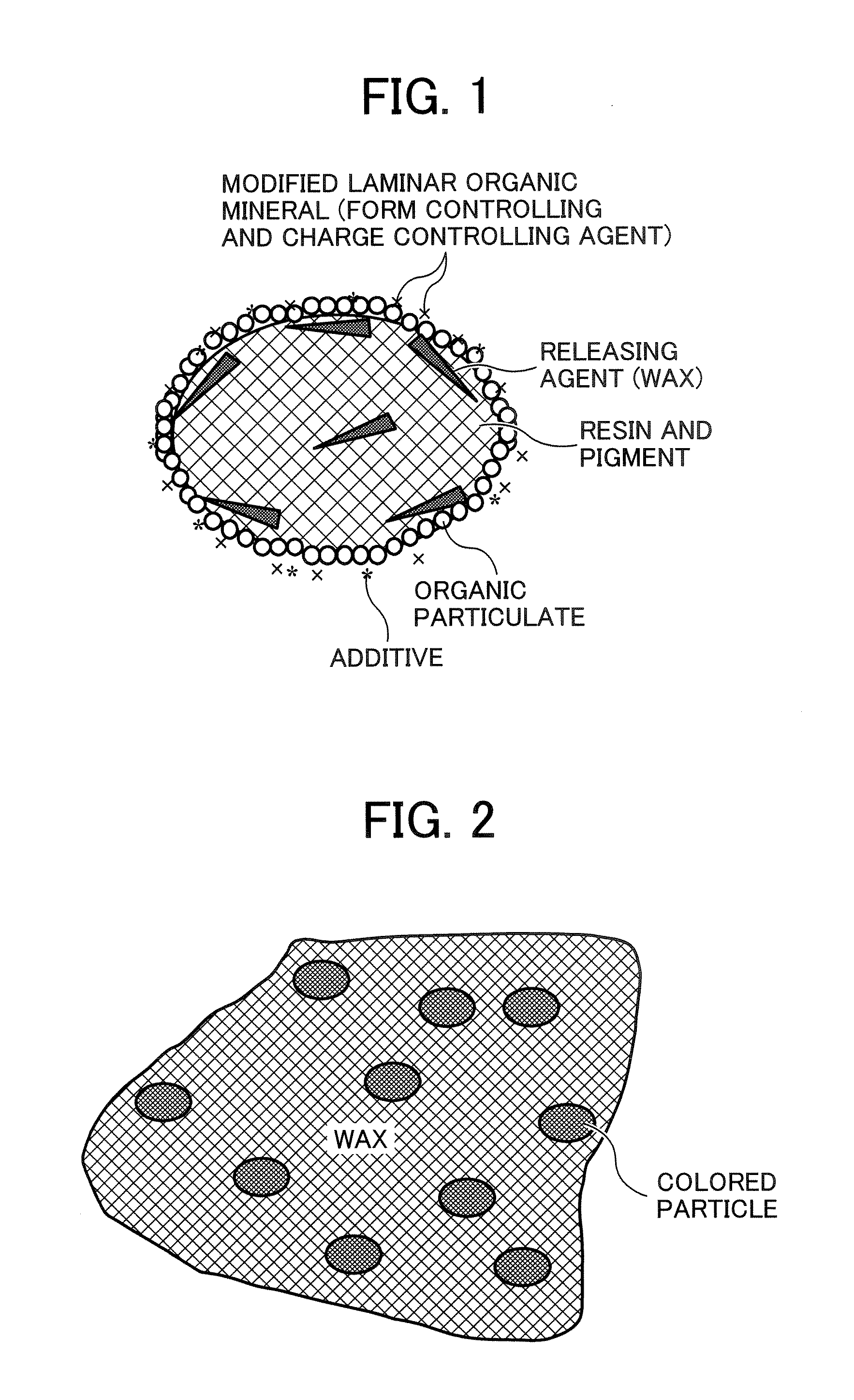
A toner containing a toner particle containing a binder resin, a colorant, a releasing agent and a laminar inorganic mineral in which part or all ions present between layers are modified by organic ions. The toner particle has a structure such that when the particle is heated at a temperature ranging from 65 to 90° C. the releasing agent is melted on the outside of the toner particle to form a particle having a sea-island structure.

Description

BACKGROUND OF THE INVENTION [0001] 1. Field of the Invention [0002] The present invention relates to a toner and a method of manufacturing the toner. [0003] 2. Discussion of the Background [0004] In a contact pressure and heating method by a heating roller in the electrophotography, a toner image is fixed such that the surface of a heating roller having a releasing property to a toner is brought into contact with the toner image on a recording medium upon application of heat and pressure while the recording medium passes the heating roller. This method is extremely thermally efficient so that a toner image is quickly fixed since the toner image is melted and fixed on a recording medium while the surface of the heating roller is contacted with the toner image under pressure. [0005] However, in this contact pressure and heating method, the surface of a heating roller and a toner image are contacted in a melting state of toner upon application of pressure. Part of the toner image can b...

Claims


Application Information

Patent Timeline
IPC IPC(8): G03G9/087
CPCG03G9/0804G03G9/0808G03G9/0819G03G9/0821G03G9/0825G03G9/08782G03G9/09791G03G9/08795G03G9/08797G03G9/09708G03G9/09716G03G9/09725G03G9/09783G03G9/08793
Inventor EMOTO, SHIGERUSAITOH, AKINORIWATANABE, NAOHIROYAMADA, MASAHIDEOHKI, MASAHIROINOUE, RYOTA
Owner RICOH KK
Learn More