

Aircraft Produced by Fixing Rapid Airflow Generation Wind Direction Changing Device Directly and Firmly to Side Surface or Wall Thereof
a technology of wind direction change device and airflow generation, which is applied in the direction of machines/engines, vertical landing/take-off aircraft, liquid fuel engines, etc., to achieve the effects of low weight, simple structure and high fuel efficiency
Inactive Publication Date: 2007-09-27
IKEDA KAIDOU
View PDF15 Cites 36 Cited by
- Summary
- Abstract
- Description
- Claims
- Application Information
AI Technical Summary
Benefits of technology
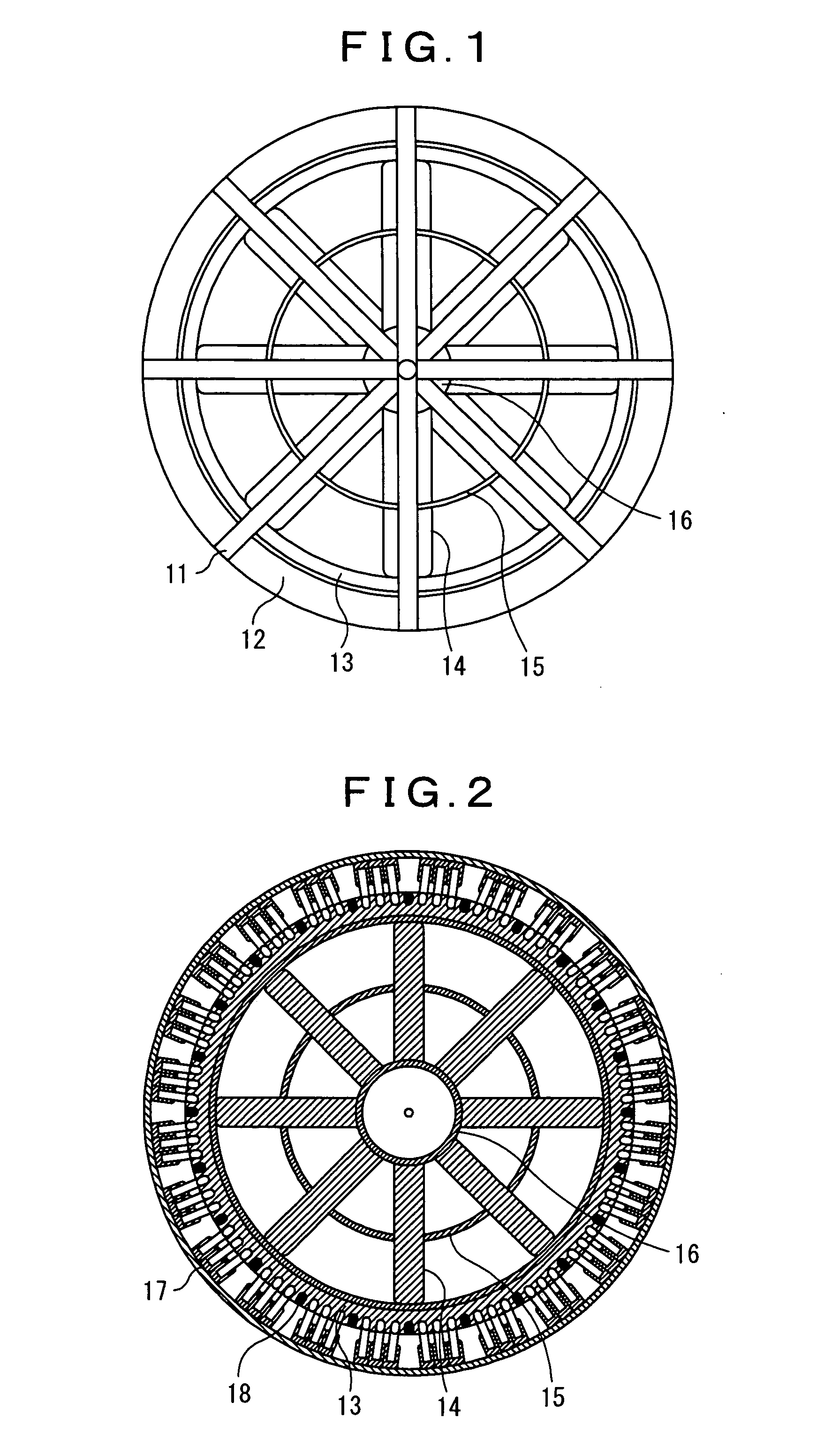
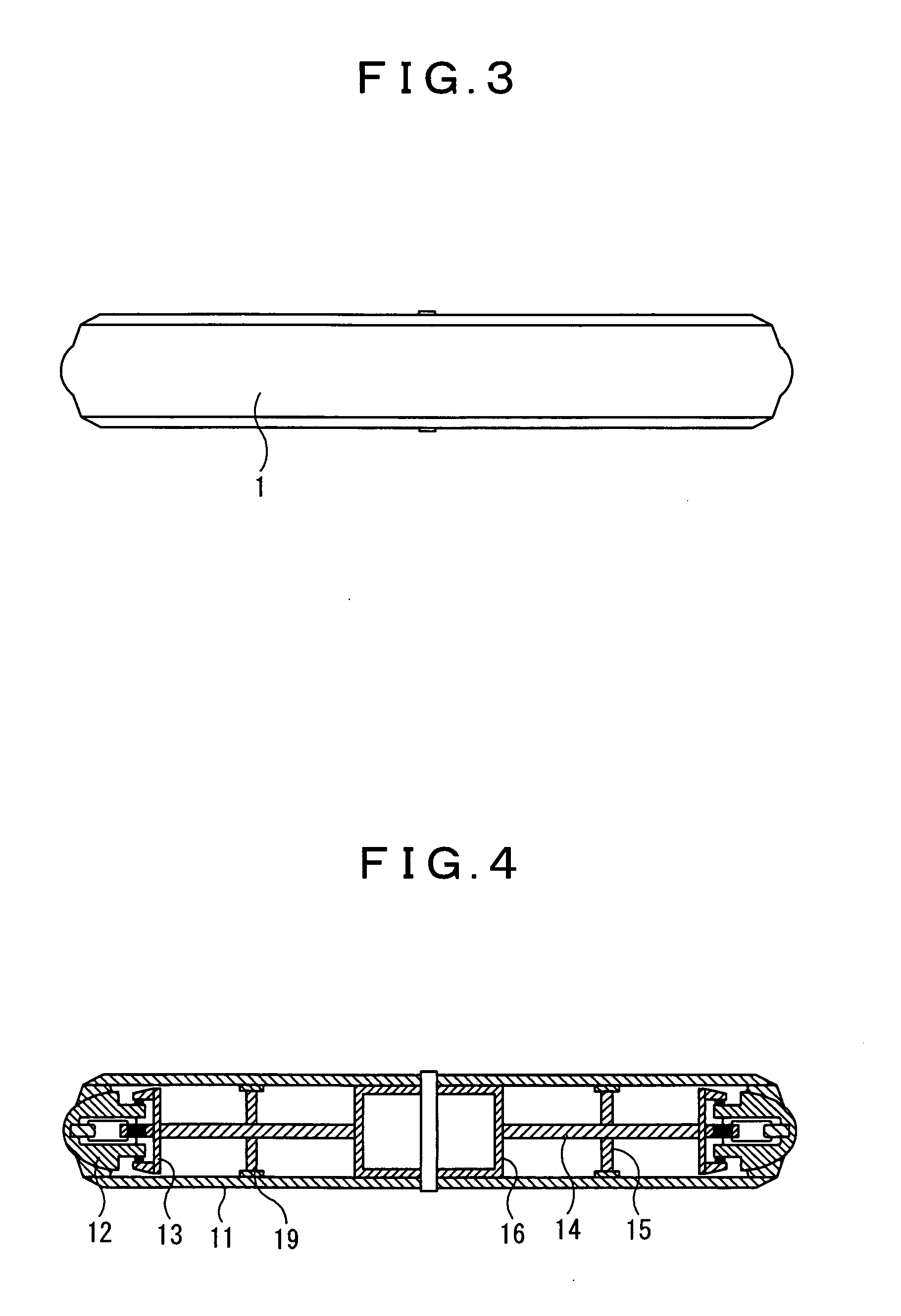
[0036] The shroud included rotor having the drive principle of linear motors has a simple structure, a small weight, and a high fuel efficiency, and further since the blade ends are not opened, there occurs no roaring shock wave that would otherwise be generated by the blade ends in the forward-moving direction of the aircraft, whereby it is quite useful to apply the rotor to helicopters and flying platforms. If the rotor is made attachable directly to the side surface (wall) of the airframe and a plurality of such rotors are operated as rapid airflow generation wind direction changing devices that can freely change airflow and wind direction, it is possible to satisfactorily show the characteristics of the shroud included rotor having the drive principle of linear motors and to achieve mass transportation without depending on lift force generating means such as a fixed wing or a balloon (hereinafter referred to collectively as fixed wing). It is further possible not only to ensure high controllability and safety but also to achieve energy saving, and various kinds of hinges that are required for conventional rotors are made unnecessary, which can facilitate production and maintenance.
Problems solved by technology
Most conventional aircrafts having a rotor such as a propeller that have been put into practical use and actual service are adapted to drive the rotor by connecting a motor to the rotational center axis of the rotor, which requires an immense amount of energy and limits the transportation capacity to a small number of passengers and cargoes for their large-sized engines.
Also, since the rotor is supported only at the rotation axis thereof, i.e., at a single point and the blade ends are open ones floating in the air, trying to significantly increase the rotation radius of propeller blades that constitute the rotor results in complicating the provision of the attack angles of the central and end portions of the blades or the width of the blades and also in having a difficult problem in, for example, choosing the material of the blades, particularly between flexibility and stiffness.
As for conventional helicopters that have been put into practical use and actual service, the angular range for safety tilting is limited to about 15 degrees from the vertical axis and the tilt angle in normal operations is about 4 to 5 degrees at a maximum, while as for flying platforms, the floor part on which passengers stand is often installed with no tilting, i.e., no degree of freedom, both of the cases being put into practical use with poor degrees of freedom for tilting.
In conventional helicopters with open blade ends, blades on the side moving forward (hereinafter referred to as forward-moving or ascending blades) and blades on the side moving backward (hereinafter referred to as backward-moving or descending blades) in an approximately horizontally rotating main rotor have their respective different air speeds, resulting in an increase in the lift force on the forward-moving blades while a reduction in the lift force on the backward-moving blades to cause an imbalance between the lift forces and requiring a device for appropriately adjusting the change in the attack angle of the blades in response to a 90-degree delay due to a gyroscopic effect (gyroscopic precession).
However, Patent Document 10 describes simply that the weight of the rotor blades results in that the rollers connected to the outer end portions of the blades are brought into contact with the U-shaped inner lower surface (inner bottom surface) of the fixed ring guides, and the mechanism cannot address expansion and contraction.
Therefore, unlike conventional helicopters with open blade ends which require various kinds of complex and fragile hinges to transmit lift forces to the airframe through the rotation axis thereof, Patent Documents 10 and 14 indicate the possibility of novel helicopters that require no hinge, but there is no sufficient disclosure about how to address expansion and contraction of the rotor blades, i.e., an entity for generating lift forces and the mechanism in which the blade end portions that are important as second support points for the rotor blades slide in the guides and pipes, which makes it extremely difficult to embody the inventions as they are currently disclosed.
Even faster tilting takes a few seconds and normal tilting takes more than about one minute.
It is therefore estimated that it takes a few seconds to tilt by 90 degrees at a maximum, and the angular range in which the rack-pinion type cylinder device can be tilted is limited because of its structure having a cylinder, whereby the tilt direction may be limited, being far from free yet with two axes.
Further, since wake flow from the fan engine has an extremely high temperature and is elongated, turning the airframe to a direction where wake flow blows against the airframe assumes great risk and thereby is simply impractical to result in a significant limitation even if the airframe may be protected by a shield plate.
However, since Patent Document 12 includes no such mechanism, the left and right rotors in Patent Document 12 have no specific characteristic different from those of the other multi-rotor systems as well as no beneficial effect relative to the other multi-rotor systems.
Although there is no particular disclosure about how to get the aircraft forward in the case of the arrangements shown in FIGS. 6 and 7, if there is provided a swash plate of a kind used in common helicopters and the rotational disk surface is tilted forward for forward moving, there is a high possibility that the aircraft is tilted backward to crash coincidentally.
The arrangement shown in FIG. 9 in which a propeller or a ducted propeller for propulsion is used without tilting the rotational disk surface becomes a little more likely, but cannot be put into practical use easily.
Therefore, Patent Document 13 provides a far more dangerous vehicle than the arrangements shown in FIGS. 6, 7, and 9 of Patent Document 12 where it is extremely difficult to achieve safer flights due to unbalanced center-of-gravity and there is an extremely high possibility that when the rotor is tilted forward, the aircraft is tilted backward to fall in a spin.
However, in the case of fan engines that use jet fuel, it is difficult to fine-adjust the engine output and there is a large time delay from an indication of increasing or reducing the output, and further it is extremely difficult to incorporate a mechanism for changing the attack angle to adjust airflow in the blades of a fan engine rotating at an extremely high speed, whereby it is extremely difficult to achieve freer flights by turning the fan engine leftward or rightward and increasing or reducing the output when changing the traveling direction of the aircraft.
Even if the operations may be facilitated by introducing a computer, the response speed of the fan engine and the rotation speed of the tilting device cannot be increased, resulting in no improvement in operationality.
Since some of the installed rotors will get forward while rotating in an approximately horizontal plane, there will occur lift force imbalances between the forward-moving and backward-moving sides of each rotor.
If the rotor is of a kind in which rotor blades are supported at a rotor mast, i.e., at a single point, the rotor mast may be damaged due to reduced strength, whereby it is necessary that the rotor blades can be supported at two points or more to reduce the loads on the rotor mast.
However, none of the candidates can address expansion and contraction of the rotor blades sufficiently and it is difficult and thereby impractical to use a rotor having a large bore horizontally.
In Patent Documents 6 and 11 among those candidates, since deficiencies in addressing expansion and contraction of the blades that has a large impact on the spacing between magnets on the static (stator) and rotational (rotor) sides are lethal because driving forces are generated in blade end portions, it is extremely difficult to perform operations with a diameter of greater than about 3 m (about 1.5 m in radius).
However, there is an angular restriction and limitation within which the rack-pinion type cylinder device according to Patent Document 4 can be tilted, and even such faster tilting takes a few seconds for tilting by 90 degrees, the rotation speed being not enough.
Accordingly, since the rotor according to Patent Document 14 cannot achieve energy saving because the drive is applied to the rotation axis thereof in a conventional manner, while in the tilting device according to Patent Document 4, the tilt angle is restricted and limited as well as the rotation speed is low, both of them cannot solve the problem and achieve the object of the present inventor.
Method used
View moreImage
Smart ImageViewing Examples

Examples
first embodiment
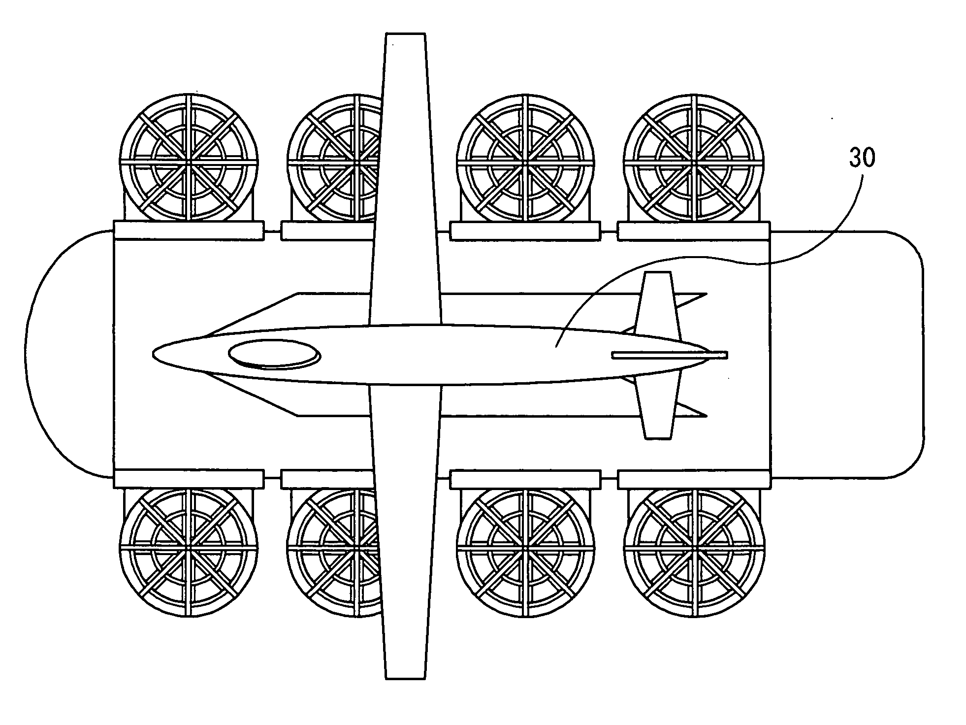
[0041] FIGS. 1 to 4 show an embodiment in the case of using a rotating duct type shroud included rotor according to Patent Document 1.
second embodiment
[0042]FIGS. 5 and 6 show an embodiment of a rapid wind direction changing device in which the blade portion of a rotating duct type shroud included rotor according to Patent Document 1 is replaced with a disk-shaped turntable.
third embodiment
[0043] FIGS. 7 to 14 show an embodiment of a rapid airflow generation wind direction changing device in which a rotating duct type shroud included rotor is placed perpendicularly on a rapid wind direction changing device.
Login to View More PUM
 Abstract
To achieve mass transportation, freer flights, and safer services in an energy-saving manner by allowing the blowout direction of a shroud included rotor having the drive principle of linear motors that can freely change airflow to be changed freely to produce a device capable of freely changing both airflow and wind direction and by attaching the produced device that can freely change airflow and wind direction to the airframe of an aircraft to control the airflow and wind direction of the device. [Means for Solution] The present invention achieves a safe and energy-saving aircraft that allows for transportation of a larger number of passengers and cargoes, freer flights in the sky, and easier control by attaching a large-sized or super-sized rapid airflow generation wind direction changing device with a diameter of greater than 10 m or 20 m to the side surface or wall of the airframe by at least one for each side, that is, at least two in total for both side surfaces or walls and by utilizing the mechanism of the rapid airflow generation wind direction changing devices that can freely control airflow and wind direction.
Description
TECHNICAL FIELD [0001] The present invention relates to a method for achieving an aircraft capable of serving as if it were a ferry in the sky, aiming at achieving transportation of much more passengers and cargoes, freer flights, and safer services in an energy-saving manner than conventional operations using same rotors such as helicopters or flying platforms for transporting passengers and cargoes in the sky by mounting and fixing a plurality of rapid airflow generation wind direction changing devices onto the side surface or wall of the aircraft and by controlling the airflow and wind direction of each rapid airflow generation wind direction changing device, where each rapid airflow generation wind direction changing device is obtained by attaching a rotor having a shroud (hereinafter referred to as shroud included rotor having the drive principle of linear motors), which is for applying the drive principle of linear motors that can freely change airflow to the vicinities of the...
Claims
Login to View More Application Information
Patent Timeline
 Patent Type & AuthorityApplications(United States)
IPC IPC(8): B64C27/20B64C11/00B64C27/52B64C29/00F04D25/06F04D29/54
CPCB64C11/001F04D25/066B64C29/0033
InventorIKEDA, KAIDOU
OwnerIKEDA KAIDOU