Manifold and stack of electrochemical reactor cells, and electrochemical reactor system composed of these components

a technology of electrochemical reactor and stack, which is applied in the field of manifold and stack of electrochemical reactor cells, and the electrochemical reactor system composed of these components, can solve the problems of difficult to decrease the thickness and increase the porosity of flat types, prone to cell failure, and cell deformation, so as to reduce the tube size and the thickness of electrolyte, and increase the surface area. , the effect of reducing the operating temperatur

Inactive Publication Date: 2007-09-27
NAT INST OF ADVANCED IND SCI & TECH
View PDF4 Cites 40 Cited by
  • Summary
  • Abstract
  • Description
  • Claims
  • Application Information

AI Technical Summary

Benefits of technology

[0087](6) Allowing a large increase in surface area per unit volume by reducing the tube ...

Problems solved by technology

However the anode support-type SOFCs with high electrical power output that have been reported so far are of the flat type, and are liable to cell failure under rapid operating cycle conditions.
Cell failure occurs when the commonly used nickel cermet undergoes large volume changes due to temperature changes and cycling in an oxygen-reduction atmosphere, resulting in cell deformation.
An extremely important technical issue is therefore to find a way of enlarging and stacking flat cells while maintaining their properties.
Controlling the electrode structure of the anode support substrate and making it thinner are important ways of improving the properties, but it has been difficult to decreas...

Method used


Image

  • Manifold and stack of electrochemical reactor cells, and electrochemical reactor system composed of these components
  • Manifold and stack of electrochemical reactor cells, and electrochemical reactor system composed of these components
  • Manifold and stack of electrochemical reactor cells, and electrochemical reactor system composed of these components

Examples


example 1

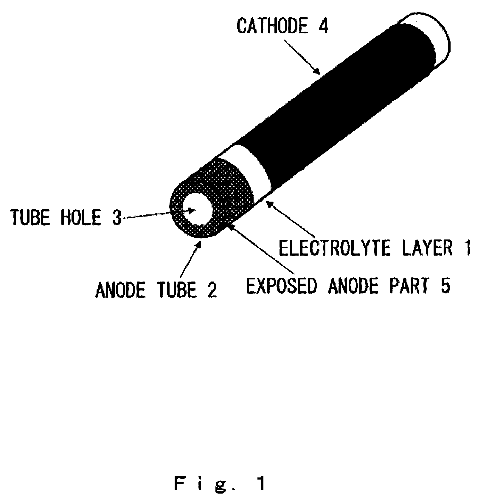
[0103]In this example, a tube-type electrochemical reactor cell was prepared by the following procedures (see FIG. 6). First, nitrocellulose was added as a binder to NiO (Wako) and a powder having a CeO2-10 mol % Gd2O3 (GDC) composition (Anan Kasei), and this was kneaded with water to a clay consistency and formed into a tube-shaped molded body (anode tube) by extrusion molding. The resulting tube-shaped molded body had a diameter of 2 mm and a tube thickness of 0.5 mm (outer diameter 2 mm, bore 1 mm).

[0104]Next, the opening at one end of the resulting tube-shaped molded body was sealed with vinyl acetate, and this tube was dipped in slurry comprising a solid electrolyte with a GDC composition to dip coat it with an electrolyte layer-forming layer and obtain an electrolyte-coated molded tube. 5 mm at the other end of the porous anode tube was left bare, forming the exposed anode part.

[0105]Next, this molded tube was dried and baked for 6 hours at 1450° C. to obtain an electrolyte-co...

example 2

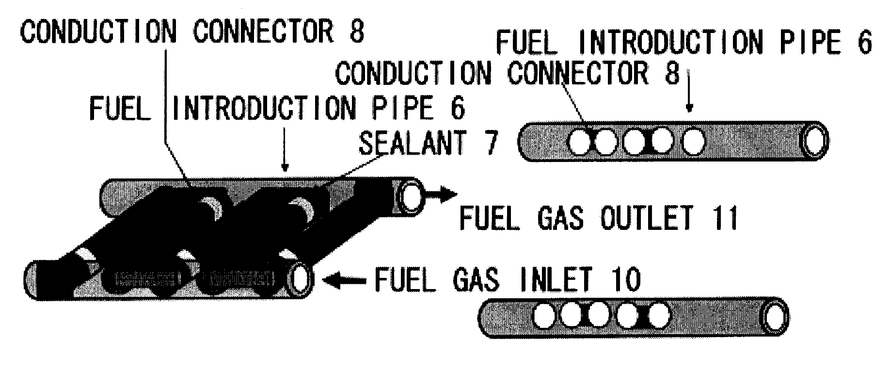
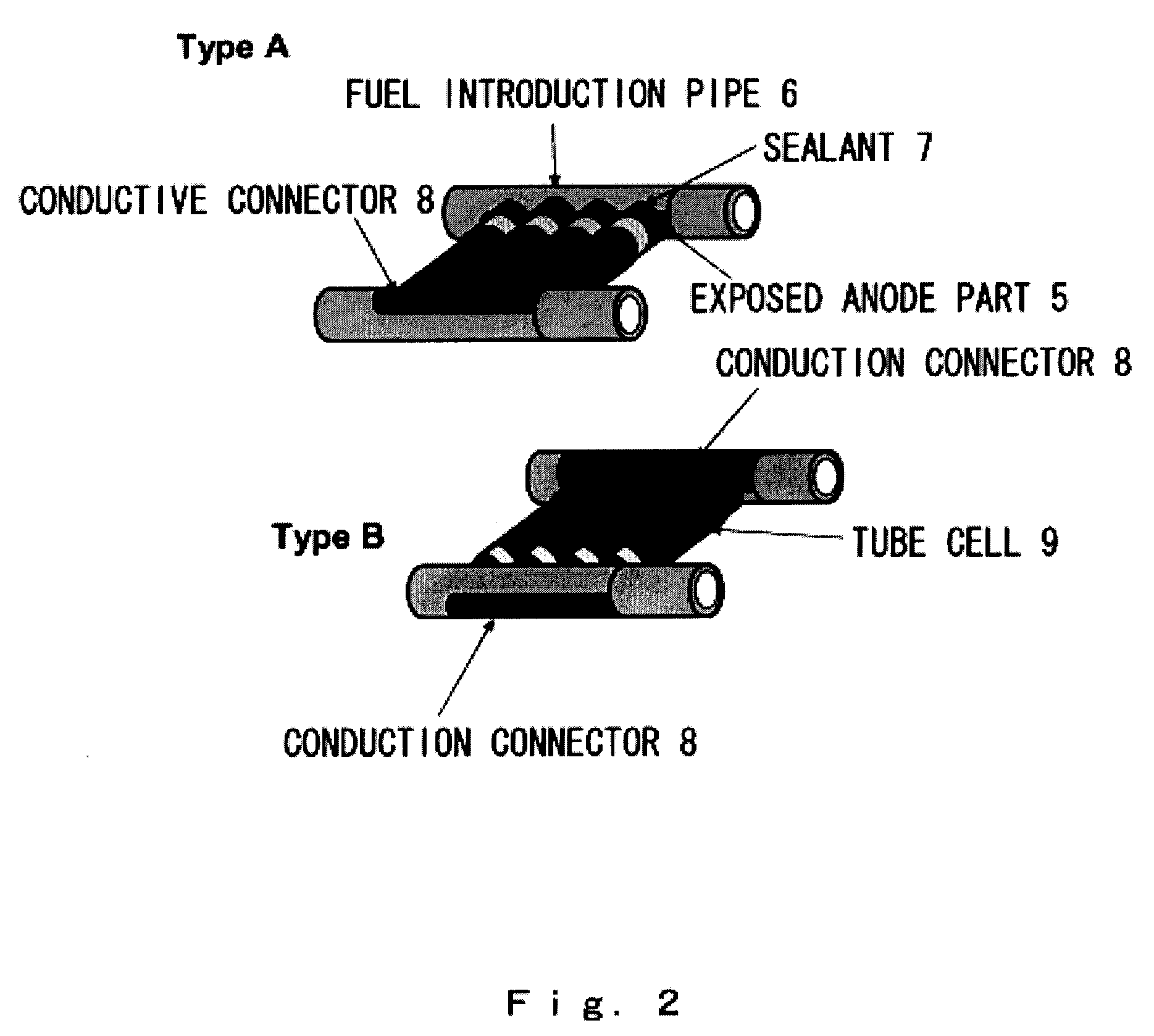
[0106]The tube cells obtained in Example 1 were arranged in parallel and connected to a gas introduction pipe (fuel introduction pipe) (FIG. 12). The connections were sealed with glass paste to fix the tube-type cells to the gas introduction pipe. Electrodes for current collection were attached by applying silver paste to the gas introduction pipe and the tube cell ends. The two units in FIG. 12 each have conductive connectors attached symmetrically, thus allowing easy serial connection between these units when they are superimposed as shown in FIG. 13.

example 3

[0107]The tube cells obtained in Example 1 were connected to a gas introduction pipe with adjacent cells reversed (FIG. 14). The connections were sealed with glass paste to fix the tube-type cells to the gas introduction pipe. The tubes could then be serially connected by applying silver paste to the gas introduction pipe and tube cell ends in order to electrically connect adjacent tubes to one another. FIG. 14 shows a stack of four serially connected tube cells. 3.6 to 4 V of electrical output can be obtained with these four tube cells.

[0108]Embodiments of the present invention were explained in detail above, but the present invention is not limited to these embodiments, and various modifications are possible to the extent that the intent of the invention is not violated. For example, in these embodiments the examples all involve single units or stacks, but the same procedures could be followed to construct a structure of superimposed stacks.


PUM


Abstract

The present invention provides a smaller and more efficient tube-type electrochemical reactor cell stack, along with an electrochemical reactor system using this stack, and the invention provides an electrochemical reactor cell stack which is a structure comprising electrochemical reactor cells with a tube structure composed of an anode (fuel electrode), a dense ion conductor (electrolyte) and a cathode (air electrode) arranged in connecting holes on the side of a fuel gas pipe, wherein each tube-type cell is connected in parallel or series electrically by means of a conduction connector, along with a manifold for tube-type cells and an electrochemical reactor system using it, and the use of a manifold and stack structure with high industrial productivity allows the small tube-type cells to be highly integrated, so that a highly efficient solid oxide fuel cell or other electrochemical reactor system can be provided.

Description

TECHNICAL FIELD[0001]The present invention relates to an electrochemical reactor cell stack and to a solid oxide fuel cell or other electrochemical reactor system composed of this reactor cell stack, and relates more specifically to a tube-type electrochemical reactor cell stack and electrochemical reaction system wherein the output per unit volume is dramatically increased by means of a stacking method which optimizes the arrangement of electrochemical reactor cells, and through the use of a manifold with excellent industrial productivity. The present invention provides a technology for constructing a microreactor cell stack structure using technology for miniaturizing tube-type reactor cells and manifold technology which simultaneously provides a more efficient arrangement of these smaller cells and a more compact structure for introducing and exhausting a fuel gas, and thereby provides an electrochemical reactor cell stack that can be used favorably as a clean energy source and e...

Claims


Application Information

Patent Timeline
IPC IPC(8): H01M8/12H01M8/24
CPCH01M8/0247H01M8/0252H01M8/12Y02E60/525H01M2300/0074H01M2300/0077Y02E60/521H01M8/243Y02E60/50H01M8/2485H01M8/2484
Inventor SUZUKI, TOSHIOYAMAGUCHI, TOSHIAKIFUJISHIRO, YOSHINOBUAWANO, MASANOBU
Owner NAT INST OF ADVANCED IND SCI & TECH
Why Eureka
Try Eureka