Method of forming carbon polymer film using plasma CVD
Active Publication Date: 2007-09-27
ASM JAPAN +1
View PDF3 Cites 331 Cited by
Summary
Abstract
Description
Claims
Application Information
AI Technical Summary
This helps you quickly interpret patents by identifying the three key elements:
Problems solved by technology
Method used
Benefits of technology
Benefits of technology
[0140] As shown in Table 1, when the CO2 flow rate was high at the high temperature, mechanical strength of a film significantly increased (the highest among the examples), and extinction coefficient (k) at 193 nm decreased as compared with those in Comparative Example 1. Although the extinction coefficient (k) at 193 nm slightly higher than in Example 1, its value is still significantly lower than in Comparative Example 1. Incidentally, in this example, the temperature was set at 450° C., advantageous effects such as those shown in this example could be obtained at a temperature of about 400° C. or higher. As with this example, a combination of the high temperature deposition and the addition of CO2 or H2 can increase mechanical strength to a higher degree than that can be achieved by the addition of CO2 or H2 alone. TABLE 1MechanicalAdditivePropertiesGasOptical PropertiesE-MechanicalFlowD / R193 nm633 nmModulusHardnessProcess(sccm)(nm / min)n-valuek-valuen-valuek-value(GPa)(GPa)Cont.04201.4380.4001.6900.0185.060.42O2154061.5430.3811.6980.0205.500.46CO23704781.5180.3621.7000.0205.820.61CO27404761.5350.3431.7100.0266.560.75CO230002911.5130.2441.7770.0759.461.29H22004951.5510.3491.6860.0156.120.60500° C.02011.3620.4171.8780.1915.770.70CO2 + 450° C.3000127.71.3680.31071.8430.23310.81.50
[0141] Process conditions in this example were essentially the same as in
Problems solved by technology
It is, however, difficult to form a thin film on a substrate because a liquid having viscosity is coated.
Method used
Image
Click on the blue label to locate the original text in one second.
Reading with bidirectional positioning of images and text.
Examples
example 1
CO2: 3,000 sccm
[0110] Process conditions in this example and film formation results are shown as follows:
[0129] In the above Example, as compared with Comparative Example 1, refractive index (n) and extinction coefficient (k) at 633 nm increased from 1.690 and 0.018 to 1.777 and 0.075, respectively; however, at 193 nm, although refractive index (n) increased from 1.438 to 1.513, extinction coefficient (k) ...
examples 2 and 3
CO2: 370 sccm and 740 sccm
[0130] Process conditions in these examples were essentially the same as in Example 1 except for the flow rate of CO2 and the deposition rate as shown in Table 1. Film formation results are also shown in Table 1.
[0131] As shown in Table 1, the above-described phenomena can be seen in these examples, which are generally or substantially proportional to the flow rate of CO2.
example 4
H2: 200 sccm
[0134] Process conditions in this example was essentially the same as in Example 1 except that H2 was used at 200 sccm as an additive gas instead of CO2 and the film formation time was 24 seconds (the deposition rate was 495 nm / min). Film formation results are shown in Table 1.
[0135] As shown in Table 1, by using H2 as an additive gas at 200 sccm, refractive index (n). and extinction coefficient (k) at 633 nm increased, whereas refractive index (n) and extinction coefficient (k) at 193 nm decreased. Interestingly, these phenomena are slightly different from those in Examples 1-3. Mechanical hardness increased. When H2 is added as an additive gas, H derived from H2 forms an H-terminal in —CH2 or promotes crosslinking as a reduction agent at —CH2, for example, present in film structures, thereby rendering its molecular structures more complex but interestingly decreasing the extinction coefficient (k) (more light passes through the film). This may be because the molecula...
PUM
Property
Measurement
Unit
Temperature
aaaaa
aaaaa
Temperature
aaaaa
aaaaa
Temperature
aaaaa
aaaaa
Abstract
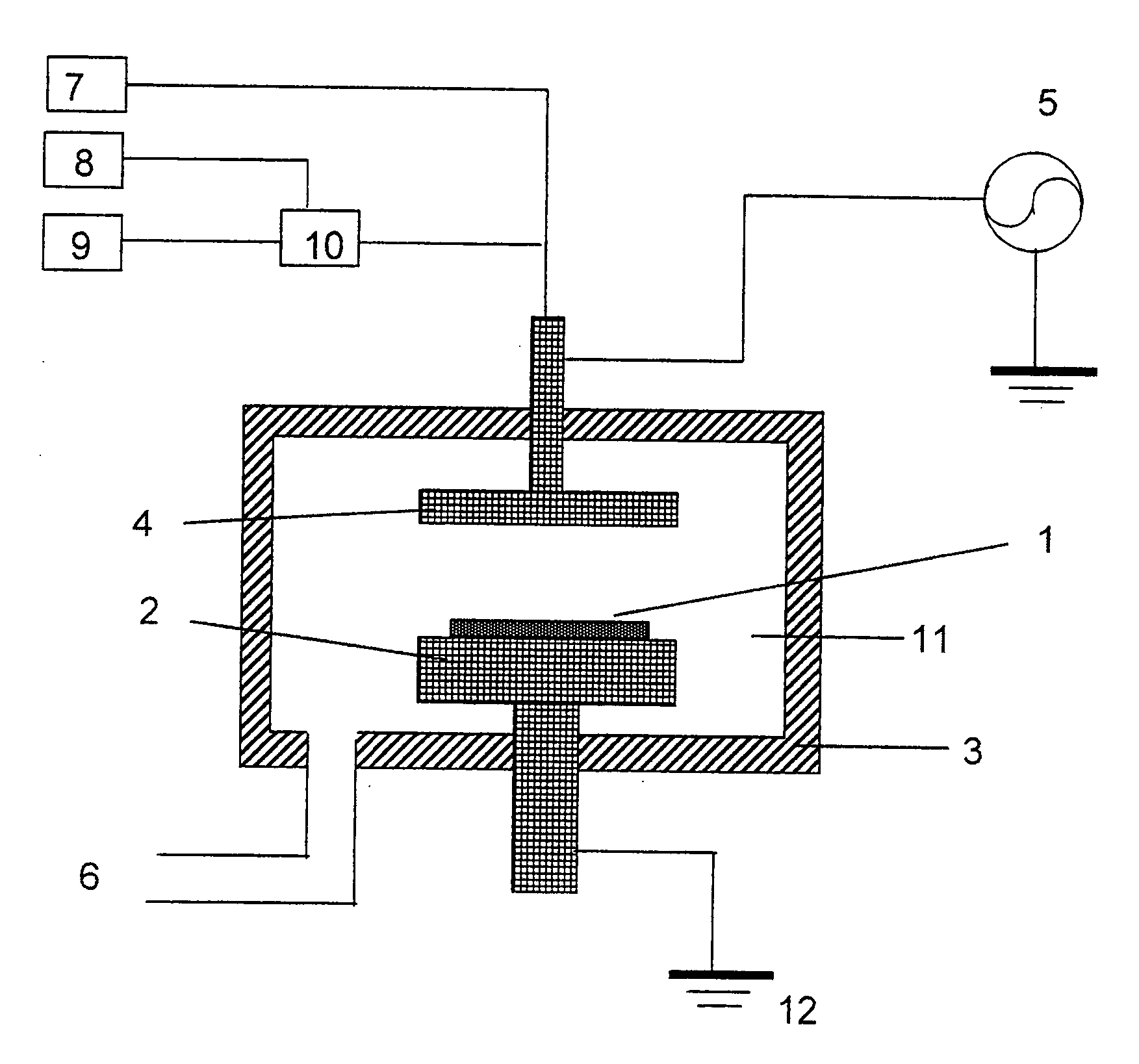
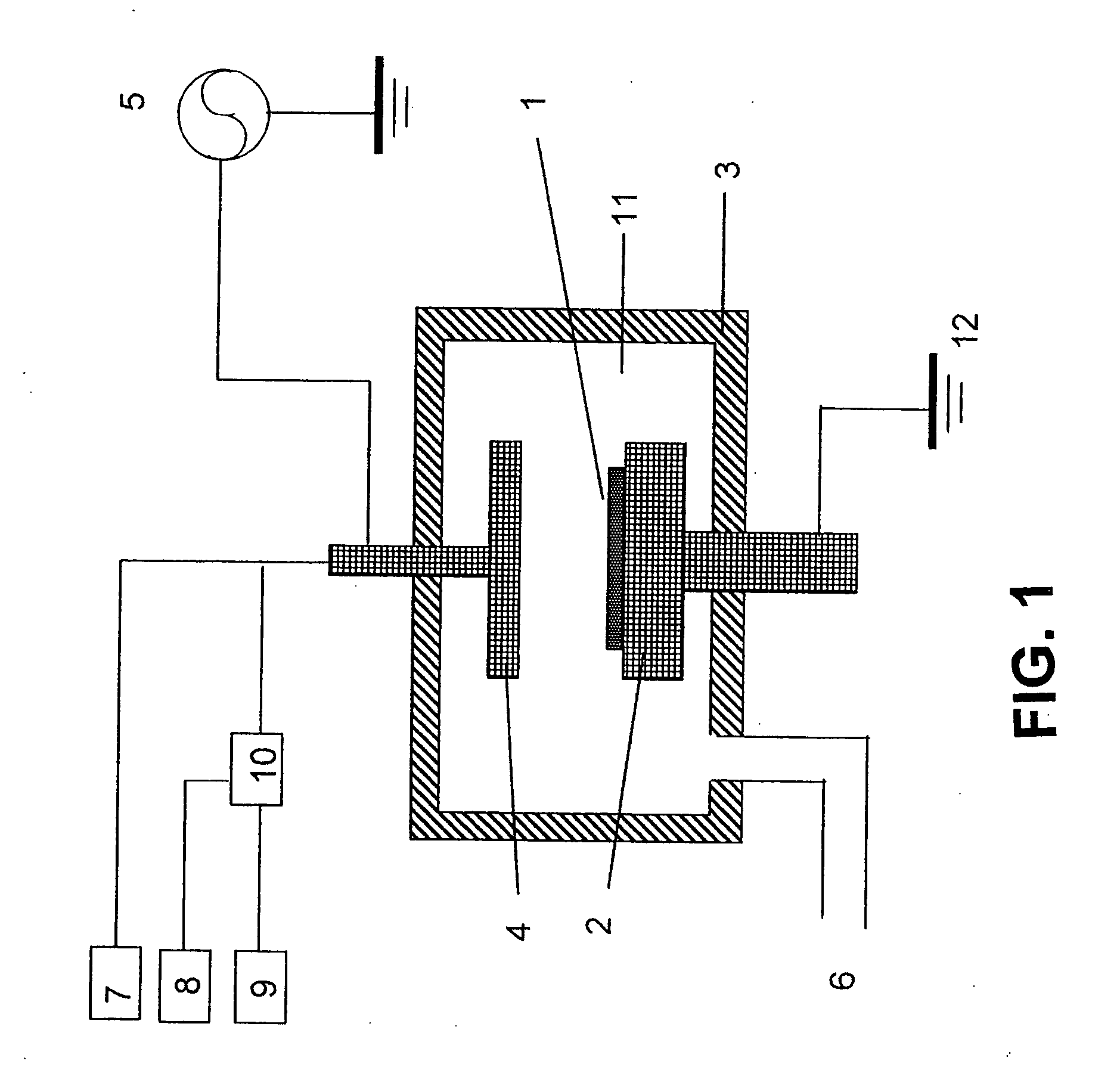
A method of forming a hydrocarbon-containing polymer film on a semiconductor substrate by a capacitively-coupled plasma CVD apparatus. The method includes the steps of: vaporizing a hydrocarbon-containing liquid monomer (CαHβXγ, wherein α and β are natural numbers of 5 or more; γ is an integer including zero; X is O, N or F) having a boiling point of about 20° C. to about 350° C. which is not substituted by a vinyl group or an acetylene group; introducing the vaporized gas and CO2 gas or H2 gas into a CVD reaction chamber inside which a substrate is placed; and forming a hydrocarbon-containing polymer film on the substrate by plasmapolymerization of the gas, thereby reducing extinction coefficient (k) at 193 nm and increasing mechanical hardness.
Description
BACKGROUND OF THE INVENTION [0001] 1. Field of the Invention [0002] The present invention relates to a method of forming a carbon polymer film by plasma CVD using a hydrocarbon-containing material having high molecular weight, and more particularly to a method of utilizing the carbon polymer film as a hard mask for semiconductorprocessing. [0003] 2. Description of the Related Art [0004] In semiconductorprocessing techniques, optical films such as antireflective films and hard masks are used. In conventional techniques, these films are formed mainly by a technique called a coating method. The coating method forms highly functional polymer films by coating a liquid material and sintering it. It is, however, difficult to form a thin film on a substrate because a liquid having viscosity is coated. As semiconductor chip sizes continue to shrink, more thinned and higher-strength films are required. [0005] As an advantageous method for achieving thinner films, use of a DLC diamond-like c...
Claims
Application Information
Patent Timeline
Application Date:The date an application was filed.
Publication Date:The date a patent or application was officially published.
First Publication Date:The earliest publication date of a patent with the same application number.
Issue Date:Publication date of the patent grant document.
PCT Entry Date:The Entry date of PCT National Phase.
Estimated Expiry Date:The statutory expiry date of a patent right according to the Patent Law, and it is the longest term of protection that the patent right can achieve without the termination of the patent right due to other reasons(Term extension factor has been taken into account ).
Invalid Date:Actual expiry date is based on effective date or publication date of legal transaction data of invalid patent.

