
Process and apparatus to recover high purity carbon dioxide

Inactive Publication Date: 2007-10-04
PRAXAIR TECH INC
View PDF12 Cites 23 Cited by
  • Summary
  • Abstract
  • Description
  • Claims
  • Application Information

AI Technical Summary

Benefits of technology

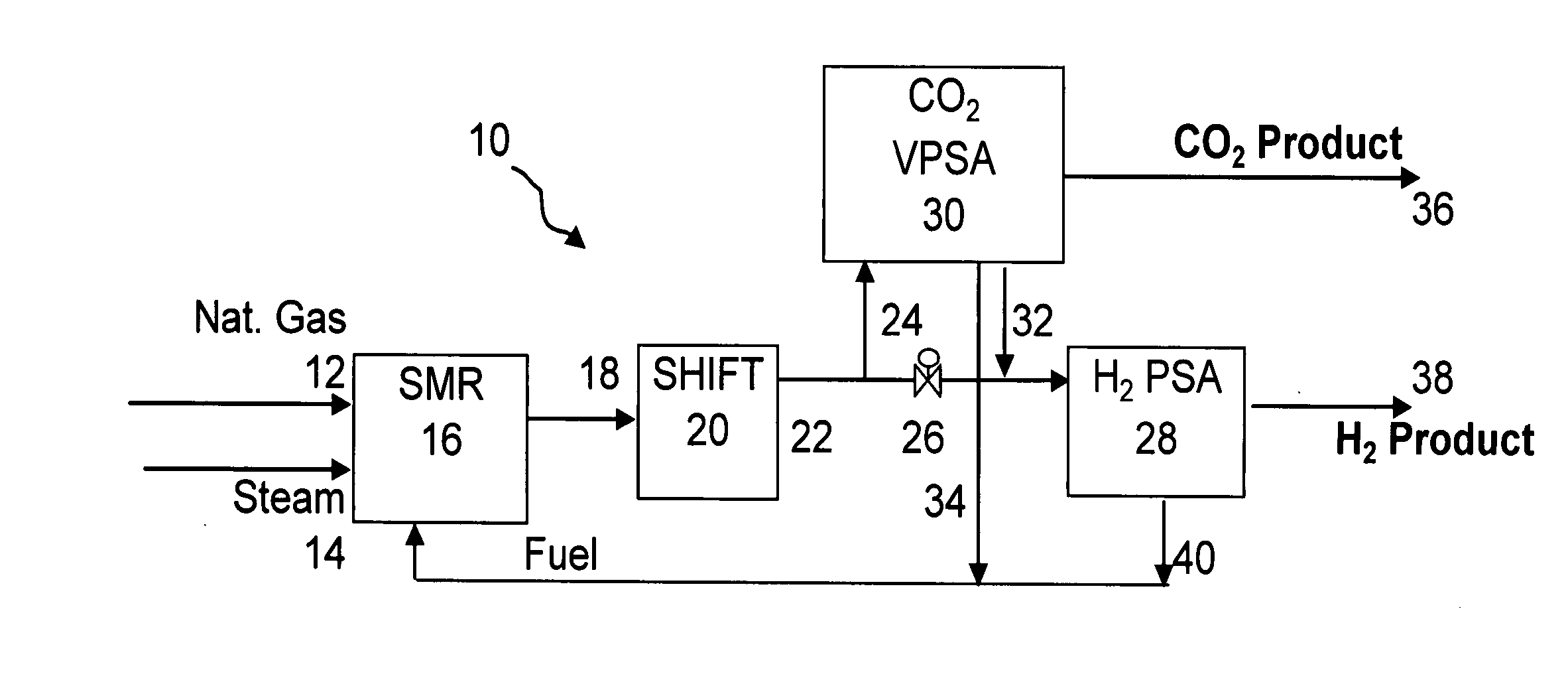
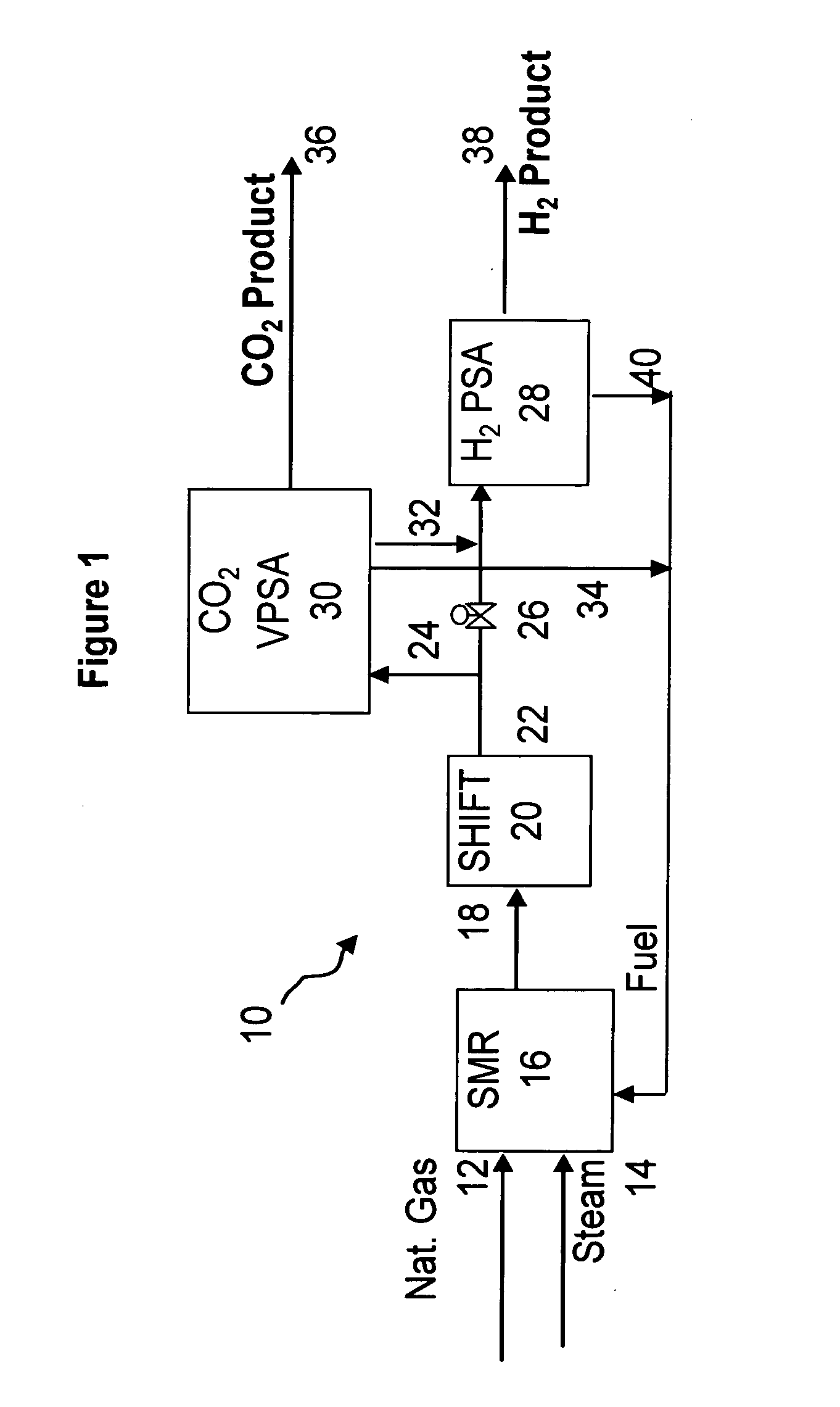
[0017] When the CO2 VPSA unit is installed between an SMR / shift reactor and a H2 PSA unit, hydrogen recovery is expected to be increased by extracting CO2, thereby increasing hydrogen partial pressure in the H2 PSA feed stream. The recovered CO2 can be further upgraded, sequestered or used in applications such as enhanced oil recovery (EOR).
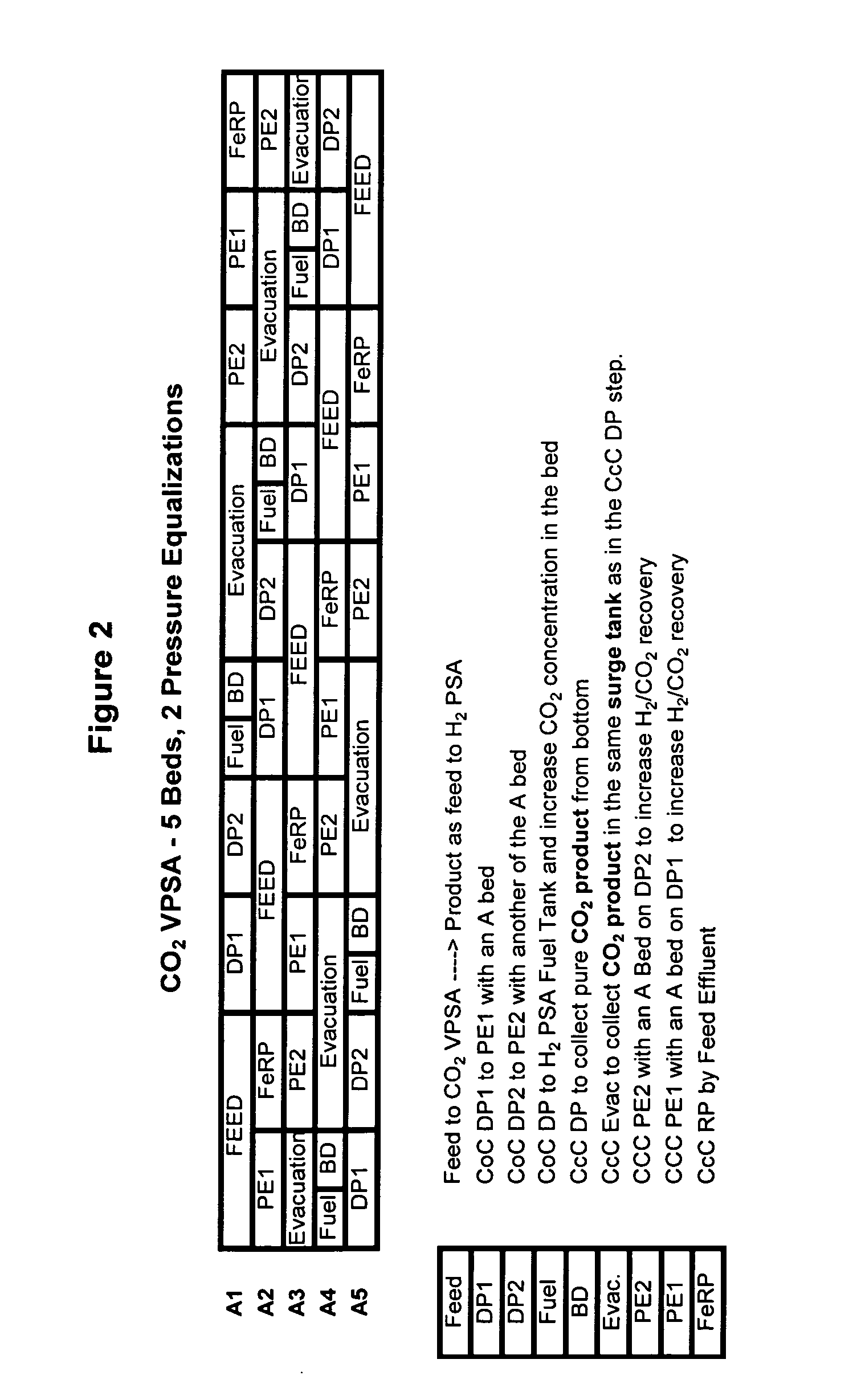
[0019] Consequently, the need for rinse, purge and / or recycle steps as used in the prior art can be eliminated. This in turn allows for the elimination of certain pieces of rotating machines (e.g., rinse compressor, purge compressor, recycle compressor) and associated power requirements, thereby providing a process and apparatus which is expected to be simpler to operate and more efficient than prior art systems. The proposed processes do not require steam and thus are expected to reduce the cost of CO2 separation. To increase CO2 recovery and reduce H2 losses, the present invention uses the depressurized gas to build up or increase the pressure in low-pressure beds. The bed depressurization therefore increases CO2 concentration in the product, and by equalizing with other beds in the unit, at the same time, increases CO2 recovery since this gas is not wasted.
[0020] In preferred embodiments in which the CO2 VPSA apparatus is installed between a steam methane reformer (SMR) / shift reactor and a H2 PSA unit, the amount of CO2 in the feed stream to the H2 PSA unit is reduced, thereby allowing for increased recovery of H2 from the H2 PSA unit. In other embodiments of the present invention, a feed stream can be provided by a partial oxidation reactor or the like. In any of these embodiments, the feed stream to the CO2 VPSA unit will be a stream containing at least hydrogen and carbon dioxide at high pressure (for example, 100-500 psia). By eliminating the hardware (i.e. rotating machinery) as mentioned hereinabove, and corresponding power requirements, the present invention is expected to more efficiently produce CO2 from synas or other streams containing at least carbon dioxide and hydrogen relative to the prior art.

Problems solved by technology

This process, however, is energy intensive.
In addition, amine units can be difficult to operate and are known to have operational problems, such as corrosion, loss of fluid and the like.

Method used


Image

  • Process and apparatus to recover high purity carbon dioxide
  • Process and apparatus to recover high purity carbon dioxide
  • Process and apparatus to recover high purity carbon dioxide

Examples


example

[0067] The nine step process cycle of FIG. 2 described above was tested on a single-bed bench scale unit and is expected to readily scale up for a five-bed system. The inner diameter (ID) of the column was 0.68 inches and the packed bed height was 5 feet. The column was packed with about 0.5 lb of commercially available 1 / 16 inch NaY pellets. The feed contained 74 mole % helium (to simulate hydrogen for safety reasons), 16 mole % CO2 and 10 mole % CH4 (to simulate CH4+CO+N2). The feed was at about 374 psia.

[0068] The process was run in a cycle manner until it reached cyclic steady state. The bed was depressurized to about 20 psia. This was followed by evacuation to about 4 psia. The quantity and concentration of the depressurized and evacuated gas was measured. By choosing the pressure at the end of the fourth step (P*) to be about 40 psia, the total CO2 produced from steps five and six was approximately 1 mmole / lb at about 93% CO2 purity and about 75% recovery. By operating the sa...


PUM

PropertyMeasurementUnit
Partial pressureaaaaaaaaaa
Pressureaaaaaaaaaa
Flow rateaaaaaaaaaa

Abstract

The present invention generally relates to vacuum pressure swing adsorption (VPSA) processes and apparatus to recover carbon dioxide having a purity of approximately ≧90 mole % from streams containing at least carbon dioxide and hydrogen (e.g., syngas). The feed to the CO2 VPSA unit can be at super ambient pressure. The CO2 VPSA unit produces three streams, a H2-enriched stream, a H2-depleted stream and a CO2 product stream. When the CO2 VPSA unit is installed between an SMR / shift reactor and a H2 PSA unit, hydrogen recovery is expected to be increased by extracting CO2, thereby increasing hydrogen partial pressure in the H2 PSA feed. The recovered CO2 can be further upgraded, sequestered or used in applications such as enhanced oil recovery (EOR).

Description

TECHNICAL FIELD [0001] The present invention generally relates to vacuum pressure swing adsorption (VPSA) processes and apparatus to recover carbon dioxide having a purity of approximately ≧90 mole percent from streams containing at least carbon dioxide and hydrogen (e.g., syngas). The feed to the CO2 VPSA unit can be at super ambient pressure. The CO2 VPSA unit produces three streams, a H2-enriched stream, a H2-depleted stream and a CO2 product stream. BACKGROUND OF THE INVENTION [0002] Steam methane reforming (SMR) is the primary process to produce hydrogen (H2) in bulk quantities. After catalytic conversion of natural gas, carbon monoxide and hydrogen is produced as follows in equation (1): CH4+H2OCO+3 H2  (1) The gas mixture is shifted (by a water-gas shift reaction) to further produce H2 according to equation (2): CO+H2OCO2+H2  (2) After the water-gas shift reaction, typical product gas has a pressure of between about 100-500 psia, a temperature of between about 60-150° F., a...

Claims


Application Information

Patent Timeline
IPC IPC(8): B01D53/02
CPCB01D53/047Y02C10/08B01D2253/10B01D2253/106B01D2256/16B01D2256/22B01D2257/504B01D2257/80B01D2259/40069B01D2259/40073B01D2259/40075B01D2259/4062C01B3/56C01B2203/0233C01B2203/0283C01B2203/043C01B2203/0475C01B2203/0811C01B2203/0827C01B2203/86B01D53/0476Y02C20/40Y02P30/00Y02P20/151
Inventor KUMAR, RAVI
Owner PRAXAIR TECH INC
Learn More