Carbon dioxide purification method

a carbon dioxide and purification method technology, applied in liquid degasification, separation processes, lighting and heating apparatuses, etc., can solve the problems of increasing the electrical power cost associated with compressing the stream, increasing the electrical power costs associated with the stream compression, and sulfur oxides and nitrogen oxides are particularly undesirable impurities, so as to reduce the energy required, reduce the overall process, and reduce the effect of refrigeration

Inactive Publication Date: 2007-10-04
PRAXAIR TECH INC
View PDF21 Cites 94 Cited by
  • Summary
  • Abstract
  • Description
  • Claims
  • Application Information

AI Technical Summary

Benefits of technology

[0015] Since the stripping column is operated at a low pressure, the carbon dioxide-rich bottoms will boil at a lower temperature than had the column been operated at the pressure of the incoming feed stream. Moreover, since the temperature of the stripping column is lower, there can be a close match between the temperature of the partly cooled feed stream that effectuates the boiling and the temperature of the boiling liquid. As a result, the overall process is more efficient because it allows recovery of carbon dioxide at highest possible pressure and reduces the energy required for further compressing carbon dioxide product. This will in turn result in an advantage that less refrigeration need be supplied through expansion to also lower the compression requirement for the incoming feed stream. Lowering the reboiler temperature also allows sufficient heat transfer from the feed stream to the reboiler of the stripping column so that high purity of carbon dioxide is achieved. Further subcooling of feed stream in the main heat exchanger after it has supplied heat for the reboiler is also advantageous as it lowers the carbon dioxide content of the overhead vapor from the stripping column and thus reduces the volume of recycle stream and thus power required to recompress it. Since the stripping column is operating at a lower temperature, more carbon dioxide will be liquefied resulting in enhanced recovery of the carbon dioxide product. Additionally, no external refrigeration is used and the process is entirely self r...

Problems solved by technology

In such an application, moisture within the carbon dioxide stream can cause corrosion problems for the pipeline.
Moreover, compressing a stream into a pipeline that contains impurities, that will invariably need to be removed, increases the electrical power costs associated with compressing the stream due to the added volume of the impurities.
Sulfur oxides and nitrogen oxides are particularly undesirable impurities in any process stream.
Such an operation results in thermal inefficiency that represents an irreversible loss that must be made up by increased refrigeration and ultimately, in increased compression and power requirements.
As a result...

Method used


Image

  • Carbon dioxide purification method
  • Carbon dioxide purification method
  • Carbon dioxide purification method

Examples


example 1

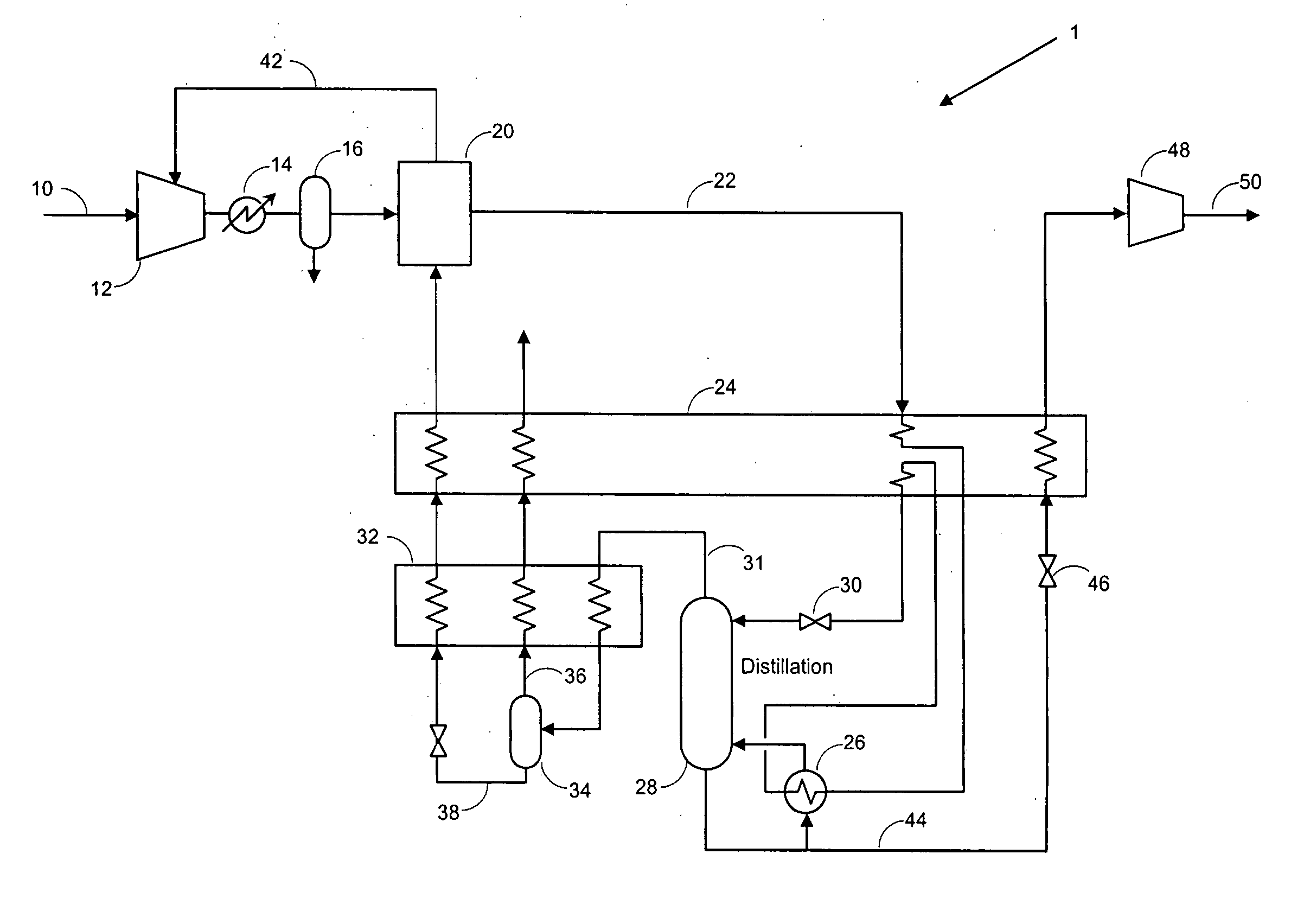
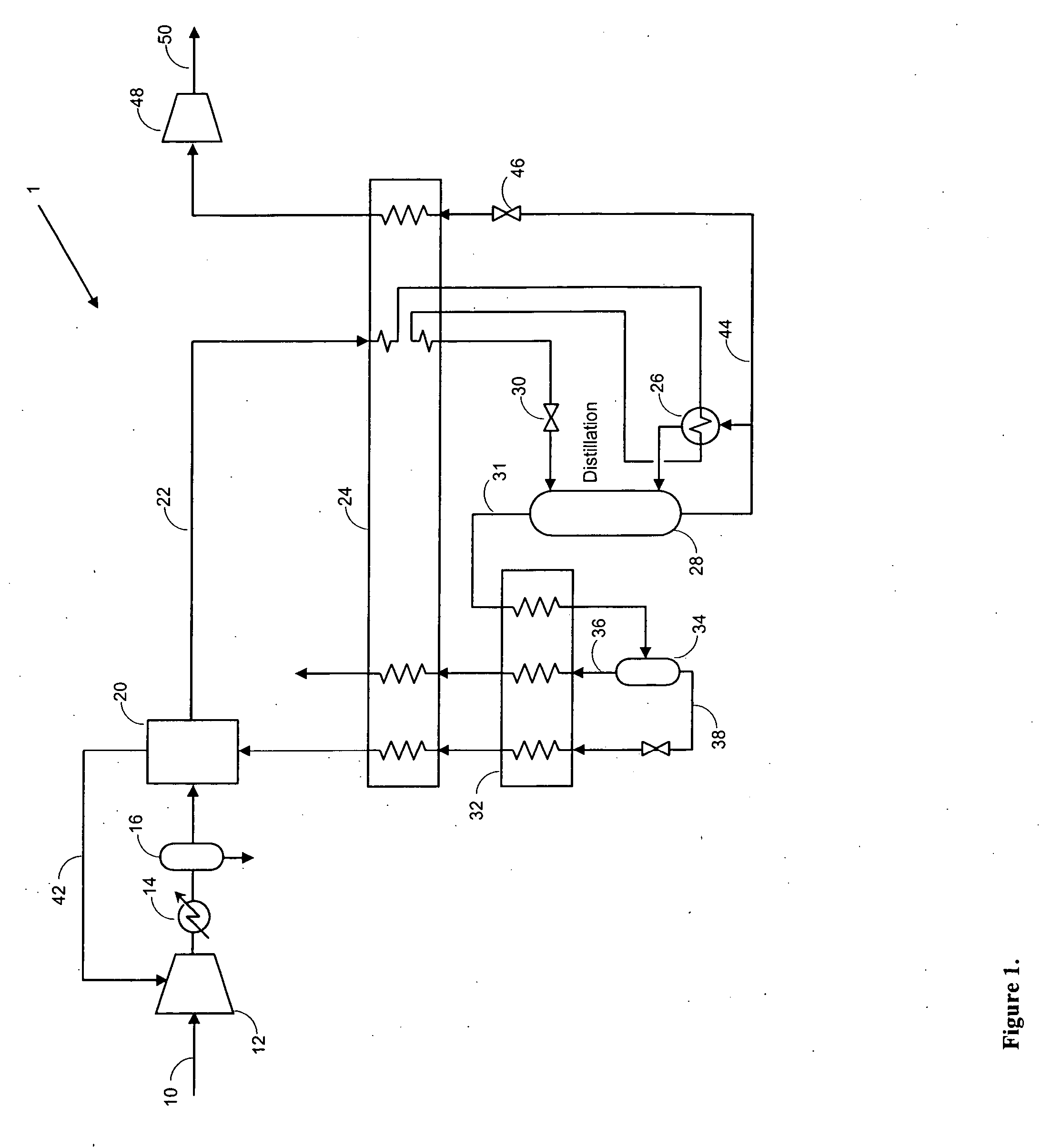
[0044] In the following example, feed stream 10 is a recycled gas from an enhanced oil recovery facility with the objective of removing methane and nitrogen from such recycled stream before re-injecting it in the oilfield. The embodiment illustrated in FIG. 1 was used for purposes of this Example. The target methane level in this example is 100 ppm in the recovered carbon dioxide and the recovery was about 93.5 percent by volume. As a result of purification, components undesirable for enhanced oil recovery, such as methane and nitrogen were removed, while C(2)+ hydrocarbons were largely retained in the recycled carbon dioxide stream. The pressure of compressed carbon dioxide stream 50 can be set depending on the reservoir pressure requirement for re-injection of the carbon dioxide. The carbon dioxide depleted stream 36 containing methane and other hydrocarbons can be sent to further processing to recover natural gas for sale. Tabular results for this example are given in Table 2.

T...

example 2

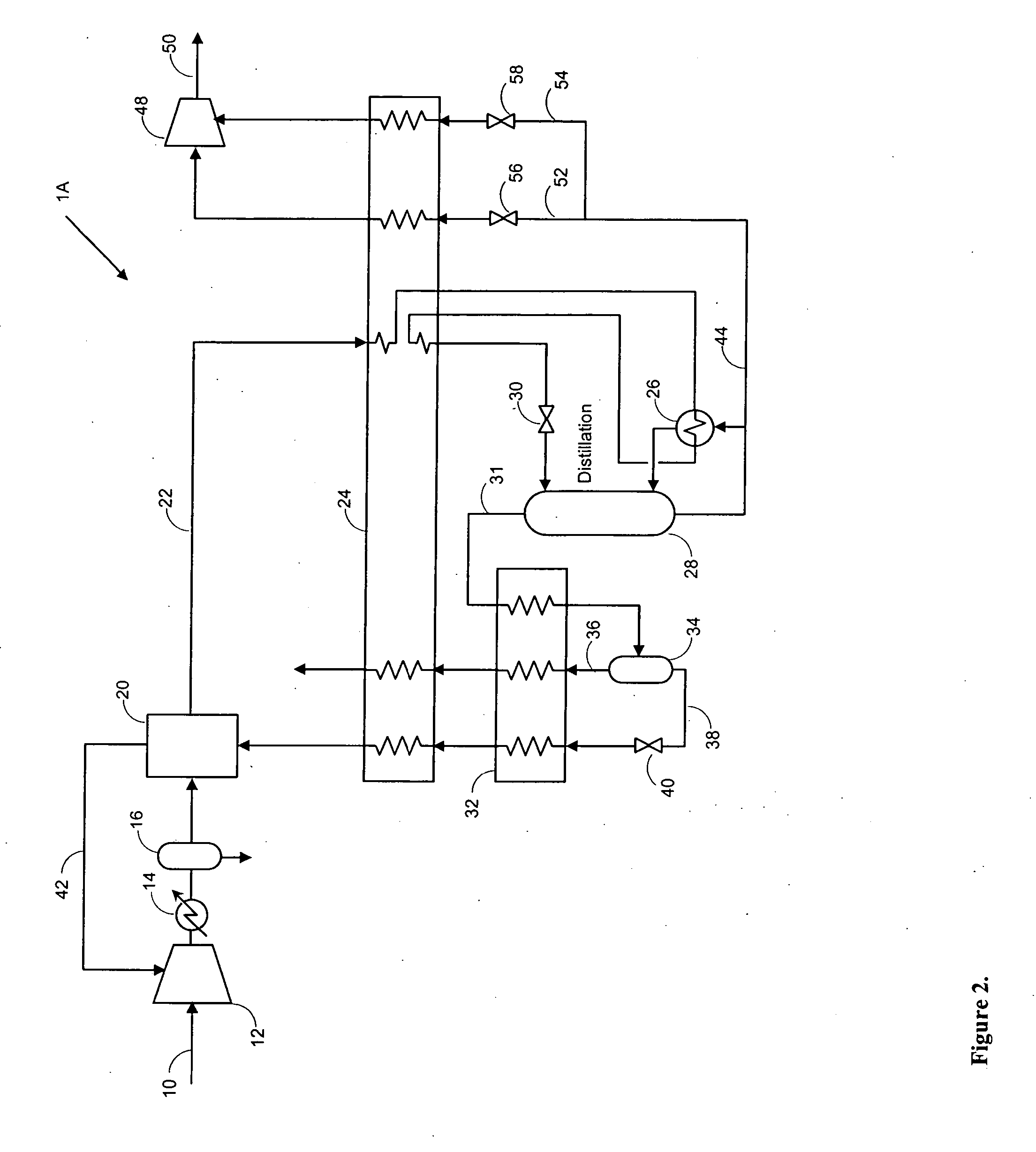
[0046] In this example, the objective is to remove oxygen, nitrogen and argon from the feed stream 10, which in this case is formed from oxy-fuel combustion flue gas, to produce purified carbon dioxide stream for EOR or sequestration. It is preferred to reduce oxygen concentration to 10 ppm or less and that was used as the specification for purification. The embodiment shown in FIG. 2 was used and the carbon dioxide recovery of about 86.5 percent on a volume basis was obtained. The carbon dioxide depleted stream 36 can be heated and then expanded for power recovery before venting to atmosphere. Tabular results are given in the following Table 2.

TABLE 2Stream102252543638Flow,1000010000404926993252720lbmol / hTemperature,959555555555° F.Pressure,14.7700180340445135psiaComposition(mol % drybasis)CO2787899.987399.987332.495.2O2550.00100.001015.31.2Argon440.01150.011512.31.4N213130.00020.000240.02.2Stream102252543638Flow,1000010000404926993252720lbmol / h

[0047] In Table 2, the physical pro...


PUM

PropertyMeasurementUnit
Temperatureaaaaaaaaaa
Electrical inductanceaaaaaaaaaa

Abstract

Method of purifying a feed stream containing carbon dioxide wherein the feed stream after having been compressed and dried is partly cooled and then used to reboil a stripping column. Thereafter, the feed stream is further cooled and expanded to a lower operational temperature of the stripping column. A carbon dioxide product stream composed of the liquid column bottoms of the stripping column is expanded at one or more pressures to generate refrigeration, then fully vaporized within the main heat exchanger and compressed by a compressor to produce a compressed carbon dioxide product. Refrigeration is recovered in the main heat exchanger from a column overhead stream extracted from the stripping column within the main heat exchanger either directly or indirectly by auxiliary processing in which carbon dioxide is further separated and optionally recycled back to the main compressor used in compressing the feed stream.

Description

FIELD OF THE INVENTION [0001] The present invention relates to a carbon dioxide purification method for purifying a feed stream containing carbon dioxide within a stripping column to produce a carbon dioxide product. More particularly, the present invention relates to such a purification method in which the feed stream is compressed and introduced into a stripping column at a pressure below the pressure of the feed stream to allow sufficient heat transfer from the feed stream to the reboiler of the stripping column to produce carbon dioxide with high purity and for recovering product carbon dioxide at superatmospheric pressure to minimize compression energy. BACKGROUND OF THE INVENTION [0002] Carbon dioxide is a valuable industrial product having a variety of uses that require that carbon dioxide to be of high purity, namely, over 95 percent pure carbon dioxide by volume. In some instances, it is necessary to remove undesirable impurities from carbon dioxide. And in some instances, ...

Claims


Application Information

Patent Timeline
IPC IPC(8): C01B31/20C01B32/50
CPCC01B31/20Y02C10/12F25J3/0223F25J3/0266F25J2200/02F25J2200/70F25J2205/02F25J2205/04F25J2205/66F25J2210/04F25J2210/70F25J2220/82F25J2230/30F25J2230/32F25J2230/80F25J2245/02F25J2270/02F25J3/0209C01B32/50F25J2240/90B01D53/002B01D2257/504Y02P20/151Y02C20/40F25J3/02
Inventor SHAH, MINISH MAHENDRAHOWARD, HENRY EDWARD
Owner PRAXAIR TECH INC
Why Eureka
Try Eureka