Plasma-treated vascular occlusion devices and methods
a vaso-occlusive device and plasma technology, applied in the direction of veterinary instruments, closures using stoppers, liquid handling, etc., can solve the problems of increasing the size of the aneurysm, increasing the risk of a burst aneurysm, and little control over the rate of dissolution of the outer layer, so as to facilitate thrombosis and improve the thrombogenic properties of the vaso-occlusive devi
- Summary
- Abstract
- Description
- Claims
- Application Information
AI Technical Summary
Benefits of technology
Problems solved by technology
Method used
Image
Examples
example 1
[0037] An embolic coil is prepared with a non-absorbable polymer as a foam coating. To prepare a 2% weight / weight solution of 85 / 15 poly(vinylidene fluoride-co-hexafluoropropylene) (available, for example, from Aldrich, St. Louis, Mo., USA), 1.04 grams of this copolymer was added to 49.34 grams of 1,4-dioxane (available from Fisher Scientific, Raritan, N.J., USA). The mixture was stirred for 24 hours in a 60° C. water bath set on a controlled-temperature heating plate. The copolymer solution was filtered through an extra-coarse thimble to remove undissolved solids. A 1% weight / weight copolymer solution was prepared by adding 10 grams of 1,4-dioxane to 10 grams of the 2% solution.
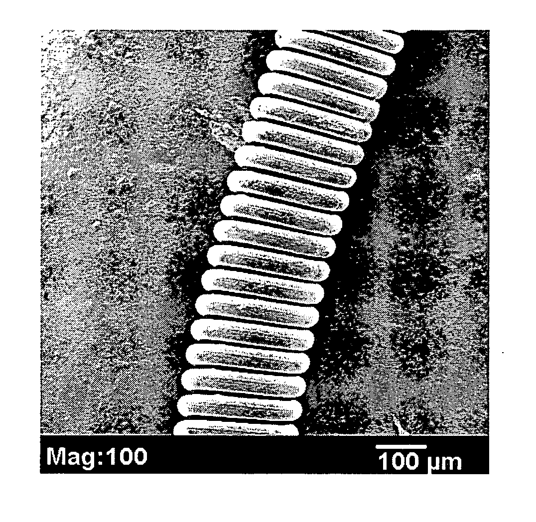
[0038] A 15 cm embolic coil (such as the coil shown in FIG. 1) was inserted into a section of PTFE (polytetrafluoroethylene) tubing (0.015 inch inner diameter, available from Zeus Industrial Products, Orangeburg, S.C., USA) that was 2 cm longer than the coil. The tubing served as mold when the copolymer sol...
example 2
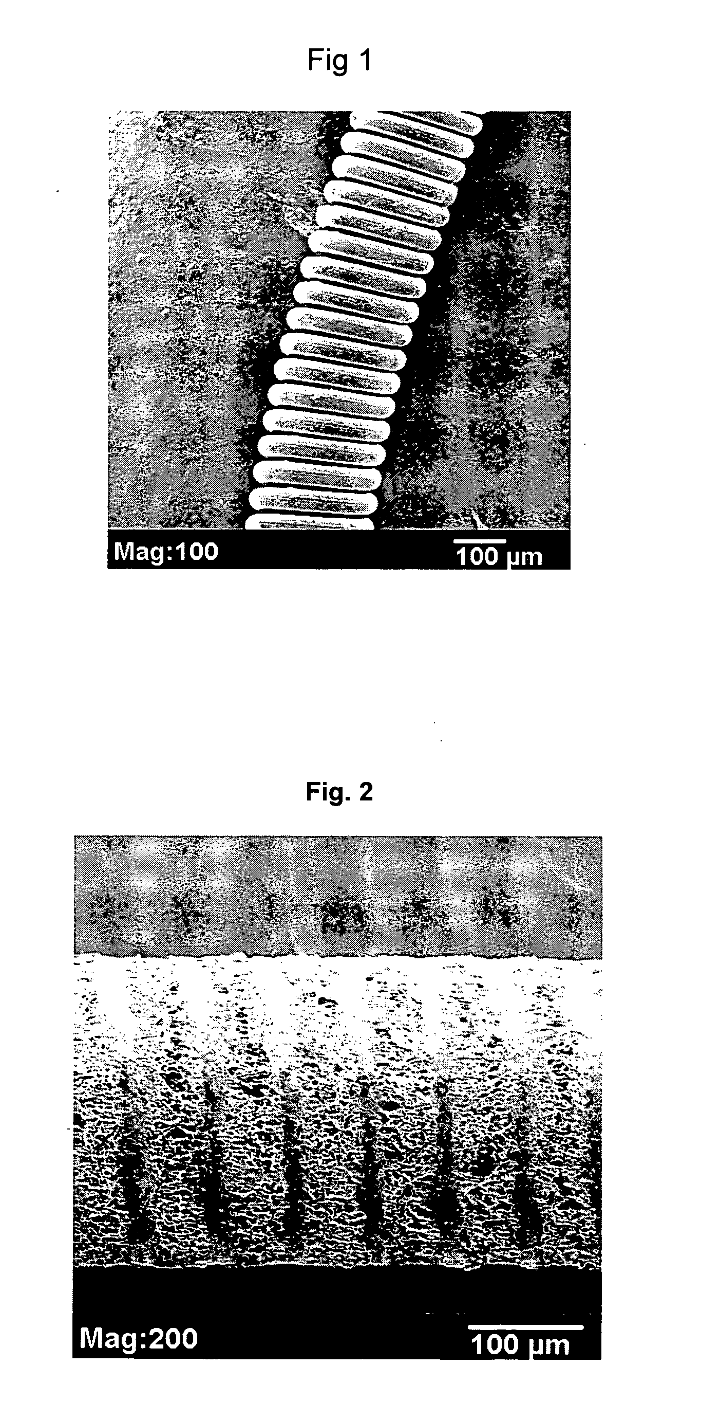
[0040] A series of foam-coated PVDF / HFP embolic coils made in accordance with Example 1 were examined using an SEM (JEOL JSM-5900LV) and evaluated. For each coil, the middle section and end sections were examined. FIG. 2 is a scanning electron micrograph (SEM) of a foam coil as prepared in this Example. As evident from FIG. 2, PVDF / HFP foam with interconnected pores was seen both in the coil lumen and outside of the coil. Some pores extended from the outer surface of the foam into the lumen of the coil.
example 3
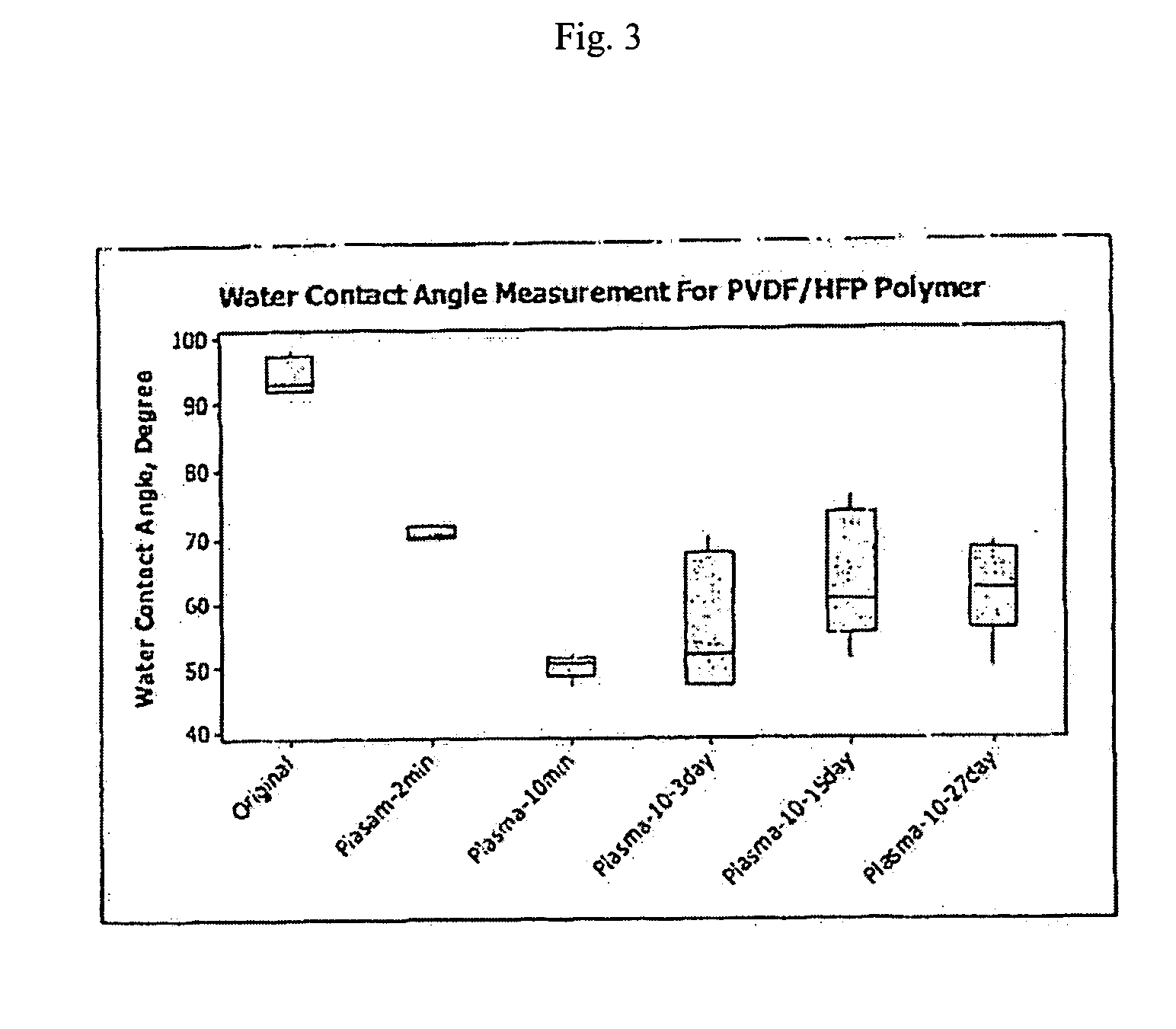
[0041] The effect of plasma treatment on water contact angles of PVDF / HFP polymer was studied using air as a gas. PVDF / HFP copolymer made in accordance with Example 1 was compressed into an approximately 1 mm film by applying a 20,000 pounds (approximately 9000 kg) force at 225° C. using a 30 ton Carver compressor (Model 2696, Carver Inc., Wabash, Ind., 46992). The films were washed sequentially with soap water, isopropyl alcohol, and chloroform.
[0042] The films were treated with plasma generated with a chromium type plasma instrument (Model HV2010, Tantec-EST, Lunderskov, Denmark). The films were treated in air at atmospheric pressure under 17 kV and 47 watts for either 2 minutes or 10 minutes.
[0043] Water contact angles (WCA) were determined using a NRL contact angle gonometer (Model 100-00 115 from Rame Hart Inc., Mountain Lakes, N.J., USA). WCA values were determined either immediately after plasma treatment or after periods of 3, 15 or 27 days. As shown in FIG. 3, plasma trea...
PUM
| Property | Measurement | Unit |
|---|---|---|
| water contact angle | aaaaa | aaaaa |
| frequency | aaaaa | aaaaa |
| power | aaaaa | aaaaa |
Abstract
Description
Claims
Application Information
 - R&D
- Intellectual Property
- Life Sciences
- Materials
- Tech Scout
- Unparalleled Data Quality
- Higher Quality Content
- 60% Fewer Hallucinations
Browse by: Latest US Patents, China's latest patents, Technical Efficacy Thesaurus, Application Domain, Technology Topic, Popular Technical Reports.
© 2025 PatSnap. All rights reserved.Legal|Privacy policy|Modern Slavery Act Transparency Statement|Sitemap|About US| Contact US: help@patsnap.com


