Methods for forming through-wafer interconnects and devices and systems having at least one dam structure

a technology of through-wafers and dam structures, which is applied in the direction of semiconductor devices, semiconductor/solid-state device details, electrical apparatus, etc., can solve the problems of molten solder being buried in the hollow, and reducing the amount of solder in the ball to complete the conductive connection, etc., to achieve the effect of eliminating cross-contamination concerns

Active Publication Date: 2007-11-15
MICRON TECH INC
View PDF48 Cites 81 Cited by
  • Summary
  • Abstract
  • Description
  • Claims
  • Application Information

AI Technical Summary

Benefits of technology

[0014] The present invention comprises methods for making through-wafer interconnects in substrates such as semiconductor wafers and other substrates. The methods include the formation of a conductive through wafer interconnect, or TWI, having a dam structure at one or both ends. The one or more dam structures may be configured for preventing leakage or loss of solder from the via or TWI during high temperature excursions such as those which typically occur during fabrication, testing and packaging. The one or more dam structures may also provide a convenient base for the attachment of solder balls and the like. Thus, the invention may be useful for enabling column grid array (CGA), ball grid array (BGA) and other types of interconnection between stacked dice or stacked circuit boards, and / or in die-to-circuit board attachments. The present invention may also be useful for simply connecting active area bond pads to back-side conductors. Interconnects so formed may be fabricated in the wafer stage of manufacture, utilizing conventional wafer thinning techniques. At least one semiconductor die including a TWI and having at least one dam structure is encompassed by the present invention, as well as systems incorporating same.
[0017] In a further aspect of the invention, at least one dam structure may be formed over at least one end of a via or TWI by electroless plating of a metal such as nickel or copper over at least one solder-filled metal end of the through holes, forming at least one cap or dam structure which may prevent drainage of solder therefrom during elevated temperatures at which solder melts. The exposed surface of the at least one dam structure may be photoresist etched to form a solder-retaining pattern to which a connector (e.g., solder ball) may be securely attached. The at least one dam structure may also be used to keep dissimilar materials located on either side thereof separated, and eliminate cross-contamination concerns. Accordingly, at least one semiconductor die or semiconductor die precursor structure (e.g., a semiconductor wafer) may be formed. Further, such a semiconductor die may be incorporated within a semiconductor device or system. For example, the methods of the invention may be particularly advantageous in the production of die-stacked devices, such as stacked DRAMs, SRAMs, PCRAMs, MRAMs, CAMs, flash memory devices, imagers, and the like. The method is also useful for simply connecting conductors on opposing surfaces of a thinnable substrate.
[0018] The methods of the invention offer substantial advantages over the prior art. The methods may solve the problems of solder leakage and may reduce an occurrence of unwanted voids in the solder. Reflow induced solder connection of a device (or wafer of devices) to another adjacent substrate or circuit board, etc. may be readily conducted without fear of solder loss at the elevated temperatures. The methods may be advantageous for enabling the production of high-density TWI arrays. Furthermore, all of the actions of the methods of the present invention may be conducted at a semiconductor wafer stage, whereby each action of the methods may simultaneously encompass all of the individual devices on the semiconductor wafer.

Problems solved by technology

Such a layer of nickel oxide may present a problem with adhesion or wetting of a molten metal (e.g., solder) thereto.
One of the problems encountered in the use of high density ball grid arrays (BGA), column grid arrays (CGA), or chip scale packaging (CSP) may occur when a through-wafer interconnect (TWI) of a substrate is connected to another substrate such as an electronic module or circuit board.
Particularly, when the solder deposited on a bond pad associated with a hollow conductive via and is heated to a reflow temperature, molten solder may be wicked into the hollow through hole, depleting the ball of sufficient solder to complete the conductive connection.
However, multiple pass solder-plugging steps are required and assembly yield may be lower than desired.
This method may sometimes result in other problems, including molten / softened solder drainage from the via by gravity or other influences and replacement by solder drawn from the solder ball attachment, compromising the solder ball electrical connection.
However, as an impediment to implementation of such a configuration, cap locations on the sheet must be precisely positioned so as to be aligned with respective through holes.
Because the solder paste is not reflowed, electrical continuity is established through particle-to-particle contact, which is not always reliable.
While a circuit board is typically manufactured at a desired final thickness, semiconductive materials such as silicon and the like are fragile materials subject to easy fracture.

Method used


Image

  • Methods for forming through-wafer interconnects and devices and systems having at least one dam structure
  • Methods for forming through-wafer interconnects and devices and systems having at least one dam structure
  • Methods for forming through-wafer interconnects and devices and systems having at least one dam structure

Examples


Embodiment Construction

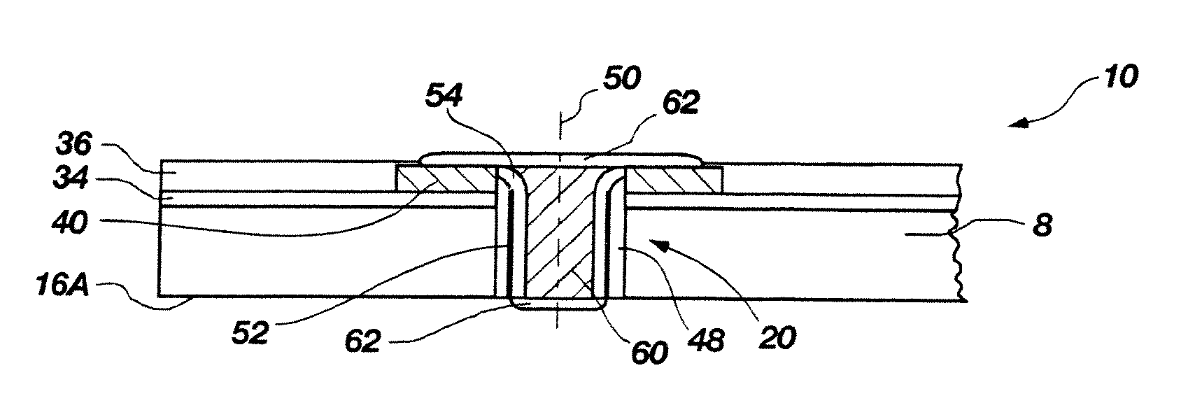
[0043] The invention comprises methods for forming through vias (“TV”) or through-wafer interconnects (“TWIs”) through a substrate structures. The term “via” is a general term denoting a conductor passing through a substrate structure. The term “through-wafer interconnect” is often used more specifically where the substrate structure is a wafer of semiconductor material (e.g., a semiconductor wafer). In this application, the terms “substrate” and “wafer” will be used interchangeably as encompassing any substrate material which may be subjected to a thinning process for reducing its thickness. Thus, the methods of the present invention relate to semiconductor devices whether in the wafer form or individualized die form that are thinnable to a final thickness. Accordingly, the term “substrate” refers not only to silicon wafers (e.g., monocrystalline silicon or polycrystalline silicon) but may also refer to silicon on insulator (“SOI”) substrates, silicon on sapphire (“SOS”) substrates...


PUM

PropertyMeasurementUnit
thicknessaaaaaaaaaa
diameteraaaaaaaaaa
thicknessaaaaaaaaaa

Abstract

A method for forming through-wafer interconnects (TWI) in a substrate. Blind holes are formed from a surface, sidewalls thereof passivated and coated with a conductive material. A vent hole is then formed from the opposite surface to intersect the blind hole. The blind hole is solder filled, followed by back thinning of the vent hole portion of the wafer to a final substrate thickness to expose the solder and conductive material at both the active surface and the thinned back side. A metal layer having a glass transition temperature greater than that of the solder may be plated to form a dam structure covering one or both ends of the TWI. Intermediate structures of semiconductor devices, semiconductor devices and systems are also disclosed.

Description

CROSS-REFERENCE TO RELATED APPLICATION [0001] This application is a continuation of application Ser. No. 11 / 218,705, filed Sep. 1, 2005, pending. The disclosure of the previously referenced U.S. patent application is hereby incorporated by reference in its entirety.FIELD OF THE INVENTION [0002] The present invention relates to semiconductor devices and fabrication methods therefor. More particularly, the invention pertains to methods for forming conductive vias in a substrate such as a semiconductor wafer or other substrate, and resulting structures. BACKGROUND [0003] Background of Related Art [0004] Semiconductor devices that have integrated circuits are produced by fabricating a large plurality of identical circuit patterns on a semiconductor wafer or other bulk substrates of semiconductor material, wherein each circuit pattern defines a die. A plethora of conventional processes is typically used, including for example, doping, photolithography, layering, etching, laser ablation, ...

Claims


Application Information

Patent Timeline
Patent Type & Authority Applications(United States)
IPC IPC(8): H01L21/3205H01L23/495
CPCH01L21/76898H01L2224/0401H01L2924/0002H01L23/481H01L2224/16238H01L2224/16146H01L2224/14181H01L2224/0557H01L2224/81815H01L2224/81191H01L2224/131H01L2224/05683H01L2224/05655H01L2224/05647H01L2224/05644H01L24/81H01L24/16H01L24/05H01L24/13H01L2924/014H01L2924/00014H01L2224/05552H01L2924/01322H01L2924/14H01L2924/00
Inventor HIATT, W. MARK
Owner MICRON TECH INC
Why Eureka
Try Eureka