Optical fourier transform device and method

a fourier transform and optical pulse technology, applied in the field of optical fourier transform devices and methods, can solve the problems of serious limitation of the available characteristic of optical fourier transform, the inability of the ln phase modulator used in conventional optical fourier transform to give a linear chirp uniformly, and the inability to accurately execute optical fourier transform to the optical pulse component in a range outside the window width, etc., to achieve accurate optical fourier transform

Active Publication Date: 2007-11-29
JAPAN SCI & TECH CORP
View PDF2 Cites 23 Cited by
  • Summary
  • Abstract
  • Description
  • Claims
  • Application Information

AI Technical Summary

Benefits of technology

[0038] In the optical Fourier transform device and method of the invention, the optical pulse whose shape is parabolic is used as the control light, and the linear chirp can be applied to the signal light by the cross phase modulation between itself and the signal light, and accordingly, more accurate optical Fourier transform can be realized. Besides, since the optical Fourier transform device and method of the invention does not require si

Problems solved by technology

However, there is a case where an LN phase modulator used in conventional optical Fourier transform can not give a linear chirp uniformly over the entire pulse. FIG. 2 is a schematic view showing the magnitude of a phase modulation (a) applied to an optical pulse by the LN phase modulator and a phase shift (b).
When this allowable window width is narrow as compared with the time width of the optical pulse, there has been a serious problem that the optical Fourier transform can not be accurately executed to the optical pulse component in a range outside the windo

Method used


Image

  • Optical fourier transform device and method
  • Optical fourier transform device and method
  • Optical fourier transform device and method

Examples


first embodiment

A. First Embodiment

(Device Structure)

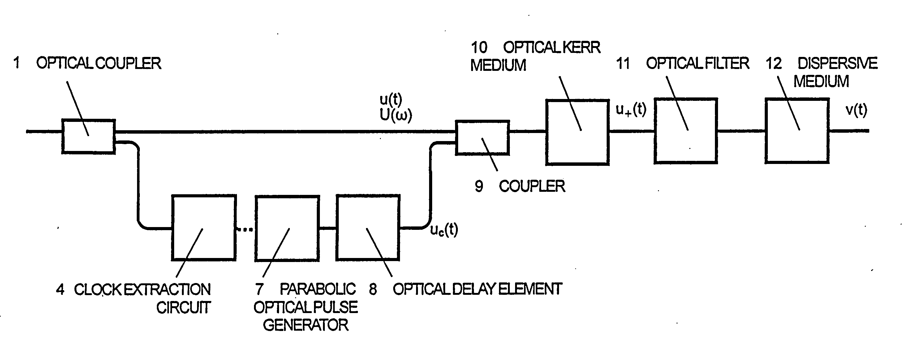
[0053]FIG. 3 is a structural view of an optical Fourier transform device of a first embodiment of the invention. The optical Fourier transform device includes an optical coupler 1, a clock extraction circuit 4, a parabolic optical pulse generator 7, an optical delay element 8, a coupler 9, an optical Kerr medium 10, an optical filter 11 and a dispersive medium 12.

[0054] The optical Kerr medium 10 is the medium having the third-order nonlinear refractive index, and for example, a single mode optical fiber, a photonic crystal fiber, a semiconductor optical amplifier, an erbium-doped optical fiber amplifier, an organic nonlinear material or the like is used.

[0055] As the dispersive medium 12, for example, a single mode optical fiber having a group-velocity dispersion characteristic in which a zero-dispersion region exists in the vicinity of a wavelength band of 1.3 μm, or a diffraction grating pair, a fiber Bragg grating or the like can be used....

second embodiment

B. Second Embodiment

[0079]FIG. 11 is a structural view of an optical Fourier transform device of a second embodiment of the invention. A difference from the optical Fourier transform device of the first embodiment is that a dispersive medium 12 is positioned in front of a coupler 9 in this embodiment. Since the other structure is similar to the foregoing, its description will be omitted. Besides, a parabolic optical pulse generator 7 can have one of the structures of FIGS. 4 to 6 similarly to the first embodiment.

[0080] Next, the operation of the optical Fourier transform device of this embodiment will be described. In FIG. 11, a signal optical pulse (wavelength λs) having a temporal waveform u(t) and a frequency spectrum U(ω) and separated by an optical coupler 1 is first launched to the dispersive medium 12. A frequency spectrum U+(ω) of the signal optical pulse at the output of the dispersive medium 12 is given by  [Mathematical⁢ ⁢formula⁢ ⁢12] U+⁡(ω)=U⁡(ω)⁢exp⁡(ⅈD⁢ ⁢ω22)(11)

N...

third embodiment

C. Third Embodiment

[0081]FIG. 12 is a structural view of an optical Fourier transform device of a third embodiment. The optical Fourier transform device of the third embodiment includes an optical coupler 1, a clock extraction circuit 4, a parabolic optical pulse generator 7, an optical delay element 8, a coupler 9, an optical Kerr medium 10, an optical filter 11, a dispersive medium 12, and optical circulators 20 and 20′. Since what are denoted by the same reference numerals as those of the optical Fourier transform device shown in FIG. 3 are similar to the foregoing, their description will be omitted.

[0082] In the figure, signal light separated by the optical coupler 1 is first launched to a port 20a of the optical circulator 20. The port 20a is connected to a port 20′a through a port 20b, the dispersive medium 12, and a port 20′b of the optical circulator 20′. The port 20′a and the port 20′c of the optical circulator 20′ are connected in a loop through the coupler 9, the optical...


PUM


Abstract

Optical Fourier transform is executed over a wide time range. A quadratic function type optical pulse generator (7) generates a control light pulse of a shape expressed by a quadratic function or a parabola according to a clock signal based on a signal light pulse from an optical coupler (1). The signal light pulse inputted is multiplexed by a multiplexer (9) with the control light pulse optically delayed by an optical delay element (8) so that the timing is matched with the signal light pulse, and introduced into an optical Kerr medium (10). In the optical Kerr medium (10), the signal light pulse inputted by the mutual phase modulation between the signal light pulse and the control light pulse is subjected to a linear phase modulation (frequency chirp) over the entire pulse or a wide time range. After that, the signal light pulse isolated by an optical filter (11) is introduced into the dispersion medium (12) having a group velocity dispersion (secondary dispersion), thereby converting the time waveform of the inputted signal light pulse into the shape of the frequency spectrum.

Description

FIELD OF THE INVENTION [0001] The present invention relates to an optical Fourier transform device and method, and particularly to an optical Fourier transform device and method which converts the temporal waveform of an optical pulse into the shape (envelope curve) of a frequency spectrum thereof and / or converts the shape of the frequency spectrum of the optical pulse into the temporal waveform thereof. BACKGROUND OF THE INVENTION [0002] Various applications using an optical Fourier transform technique to convert the temporal waveform of an optical pulse into the shape of a frequency spectrum thereof or to convert the shape of the frequency spectrum of the optical pulse into the temporal waveform thereof have been proposed in the fields of ultrahigh-speed optical communication, ultra-short pulse mode-locked laser, optical signal processing and the like. For example, in the ultrahigh-speed optical communication, there have been proposed applications to the reduction of random fluctu...

Claims


Application Information

Patent Timeline
IPC IPC(8): G02F1/35G01J11/00
CPCG02F1/3515G01J11/00
Inventor HIROOKA, TOSHIHIKONAKAZAWA, MASATAKA
Owner JAPAN SCI & TECH CORP
Why Eureka
Try Eureka