

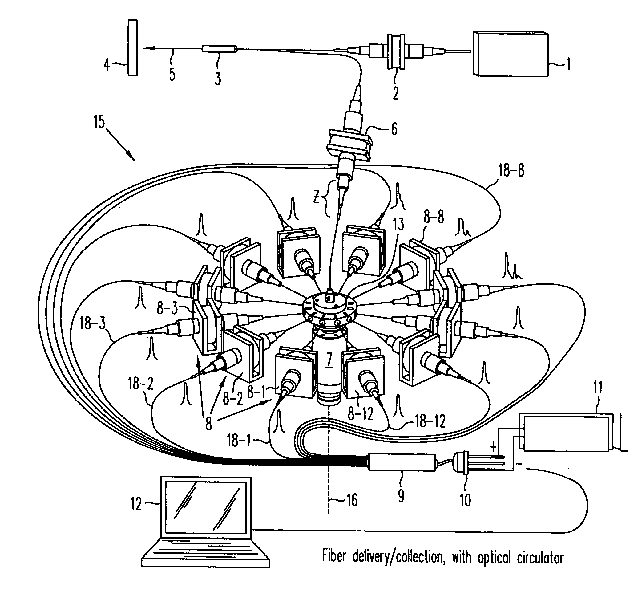
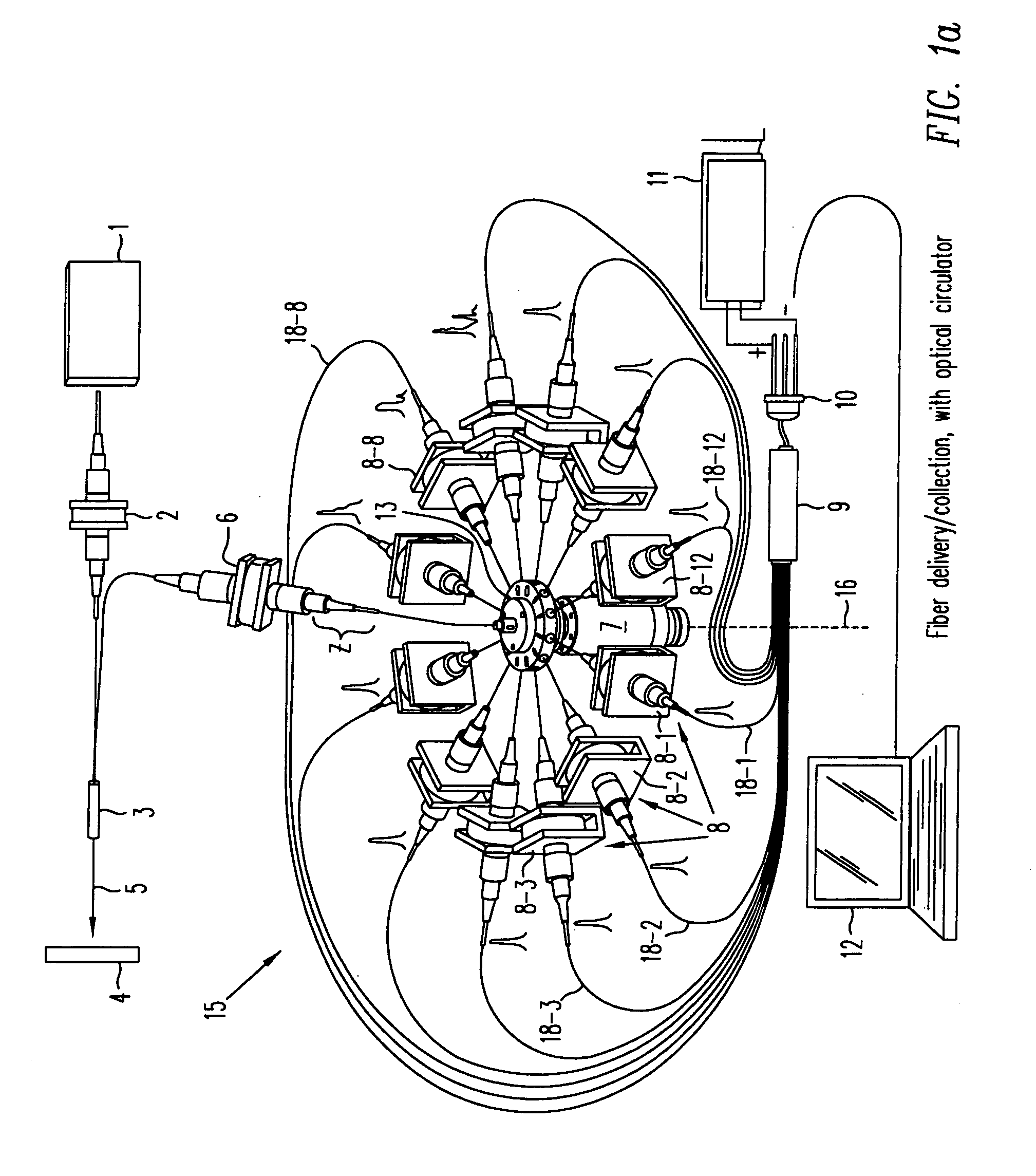
High-speed, rugged, time-resolved, raman spectrometer for sensing multiple components of a sample
a raman spectrometer and sample technology, applied in the direction of spectrometry/spectrophotometry/monochromators, instruments, optical radiation measurement, etc., can solve the problems of environmental ruggedness, simultaneous multi-component analysis of a single sample, and detection sensitivity
- Summary
- Abstract
- Description
- Claims
- Application Information
AI Technical Summary
Benefits of technology
Problems solved by technology
Method used
Image

Examples
example
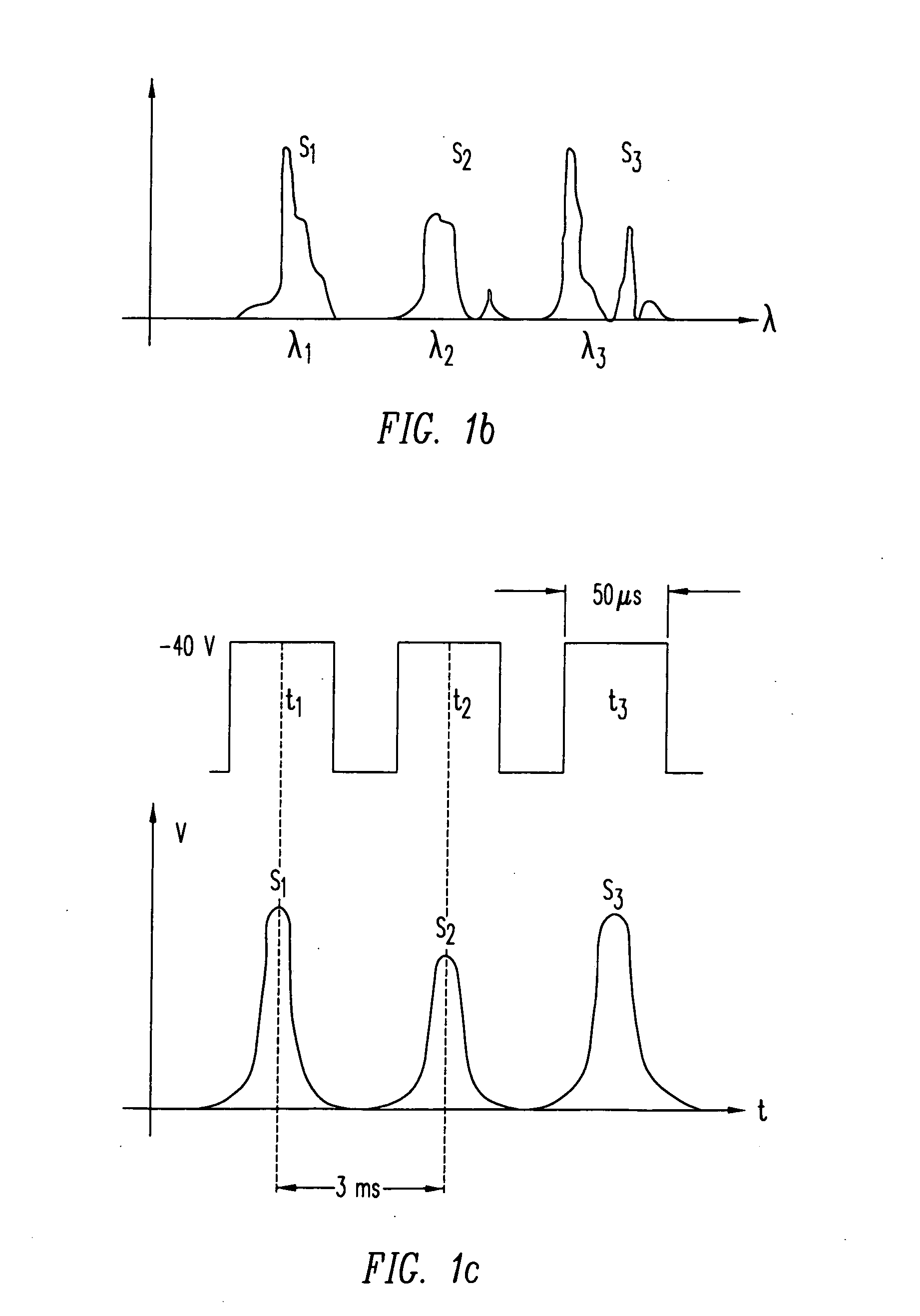
[0076]As an illustration of the procedure mentioned above, a description of a specific example will be sketched in this paragraph. Let us consider the problem of cardiovascular angiography. The substances of interest in this case are Cholesterol, Collagen and Elastin (Ch, C, and E), FIG. 7 shows the characteristic Raman spectra for these compounds. Table I shows the details of the spectra, to be used in the calculations.
TABLE IStokes Raman spectra of Collagen, Elastin and CholesterolFrequency BandCross SectionSubstance(cm−1)(×10−9 cm2 / gSr)Collagen16681.39Elastin16641.7Cholesterol14404.44Information from Ref. [a, b]. Pump wavelength is λp = 1064 nm Due to the uncertainty or variability in Molecular Weight of large bio-polymers, the cross-section is more adequately expressed in mass (g).[a] J. M. Dudik, C. R. Johnson, S. A. Asher; “Wavelength dependence of the preresonance Raman cross sections of CH3CN, SO42−, CIO4−, and NO3−”, J. Chem. Phys. 82 (4) 1732 (1985).[b] R. Manoharan, J. J....
PUM
| Property | Measurement | Unit |
|---|---|---|
| time | aaaaa | aaaaa |
| time resolution | aaaaa | aaaaa |
| time | aaaaa | aaaaa |
Abstract
Description
Claims
Application Information