Plasma etching method, plasma processing apparatus, control program and computer readable storage medium

a plasma processing apparatus and etching technology, applied in the direction of electrical equipment, decorative arts, electrical discharge tubes, etc., can solve the problems of deteriorating etching accuracy and high etching rate, and achieve high reliability, uniform etching shape, and reduce processing steps and processing time

Active Publication Date: 2007-12-13
TOKYO ELECTRON LTD
View PDF4 Cites 12 Cited by
  • Summary
  • Abstract
  • Description
  • Claims
  • Application Information

AI Technical Summary

Benefits of technology

[0007] It is, therefore, an object of the present invention to provide a plasma etching method capable of etching a silicon layer in a laminated film by using a resist film as a mask, while ensuring a sufficient selectivity against the mask and etching rate.
[0008] Another object of the present invention is to provide a plasma etching method capable of preventing an etching shape from being changed depending on a pattern density or a position on a target object.
[0019] Furthermore, by adjusting the fluorocarbon or O2 gas flow rate, the inclination angle difference of the sidewall of the etched groove caused by a difference in the pattern density and the critical dimension difference after etching caused by a difference in the position on the target object can be eliminated, thereby resulting in the uniformity of the etching shape.
[0020] Accordingly, the plasma etching method of the present invention can greatly reduce the number of the processing steps and the processing time in the silicon etching process. Furthermore, since the uniformity of the etching shape can be realized by the plasma etching method of the present invention, the present invention can be advantageously applied to the fabrication of a highly reliable semiconductor device, and cope with a trend toward the miniaturization and the high integration in the design rule of the semiconductor device.

Problems solved by technology

This is because, in case of etching the silicon by using the resist film as a mask, a selectivity against the mask is not high enough and a high etching rate could not be obtained.
Further, the gas system used for etching the insulating film differs from that used for etching the silicon, a corrosive gas is most commonly used in the silicon etching, and the etching accuracy is deteriorated by the mixing of the etching gases of the insulating film and silicon.

Method used


Image

  • Plasma etching method, plasma processing apparatus, control program and computer readable storage medium
  • Plasma etching method, plasma processing apparatus, control program and computer readable storage medium
  • Plasma etching method, plasma processing apparatus, control program and computer readable storage medium

Examples


first embodiment

[0074]FIG. 5 is a cross sectional configuration view for schematically showing a target object 110 such as the semiconductor wafer W to which a plasma etching method in accordance with a first embodiment of the present invention is applied. The target object 110 includes a silicon oxide film (SiO2 film) 102, a silicon nitride film (Si3N4 film) 103, a polycrystalline silicon layer 104, a silicon nitride film (Si3N4 film) 105 and an inorganic anti-reflection film (BARC) 106 formed in order from the bottom on a silicon substrate 101. Further, a patterned resist film (PR) 107 is formed on the anti-reflection film 106. This etching process is a single process for forming a gate electrode by using the polycrystalline silicon layer 104 as an electrode layer. Herein, the silicon oxide film (SiO2 film) 102 and the silicon nitride film (Si3N4 film) 103 serve as a gate insulating film.

[0075] In the conventional etching method applied to the target object 110 shown in FIG. 5, the anti-reflecti...

second embodiment

[0077]FIG. 7 is a cross sectional configuration view for schematically showing a target object 210 such as a semiconductor wafer to which a plasma etching method in accordance with the second embodiment is applied. The target object 210 includes a silicon oxide (SiO2) film 202, a silicon nitride (Si3N4) film 203, a silicon oxynitride (SiON) film 204, and a silicon oxide (SiO2) film 205 formed in that order from the bottom on a silicon substrate 201. Further, a patterned resist film (PR) 206 is formed on the silicon oxide (SiO2) film 205. This etching process is a single process for forming a trench 207 for burying therein an insulating film in the silicon substrate 201 by way of STI.

[0078] In the conventional etching method applied to the target object 210 shown in FIG. 7, the silicon oxide (SiO2) film 205, the silicon oxynitride (SiON) film 204, the silicon nitride (Si3N4) film 203 and the silicon oxide (SiO2) film 202 are first etched by using the resist film (PR) 206 as a mask, ...

example 1

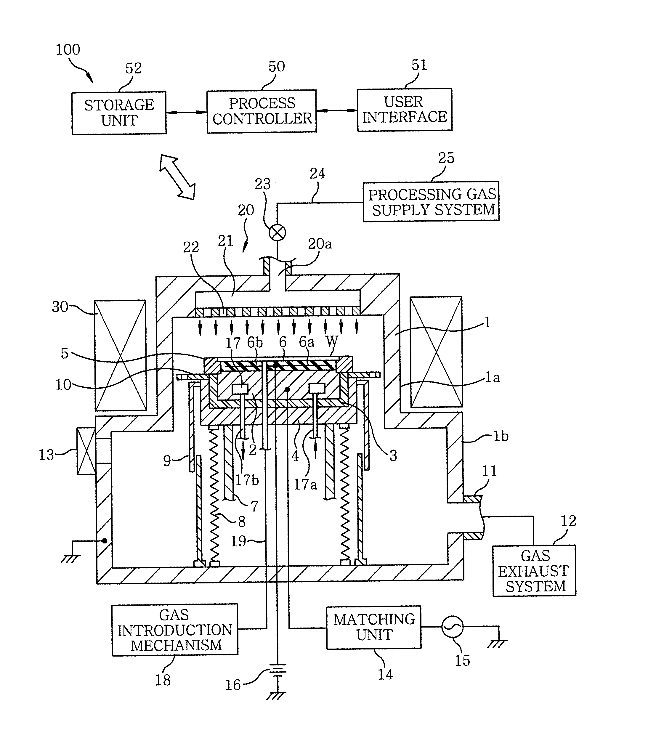
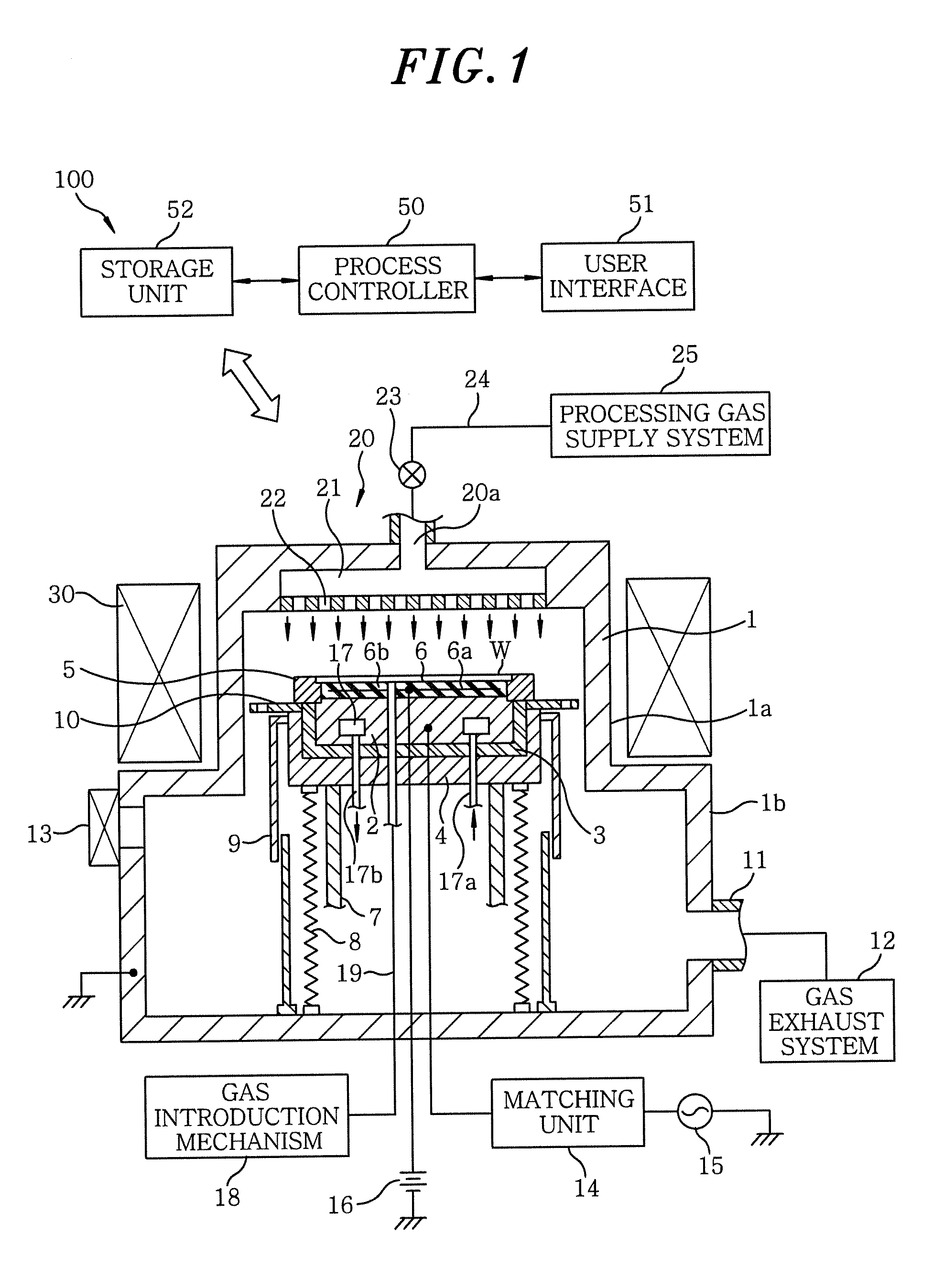
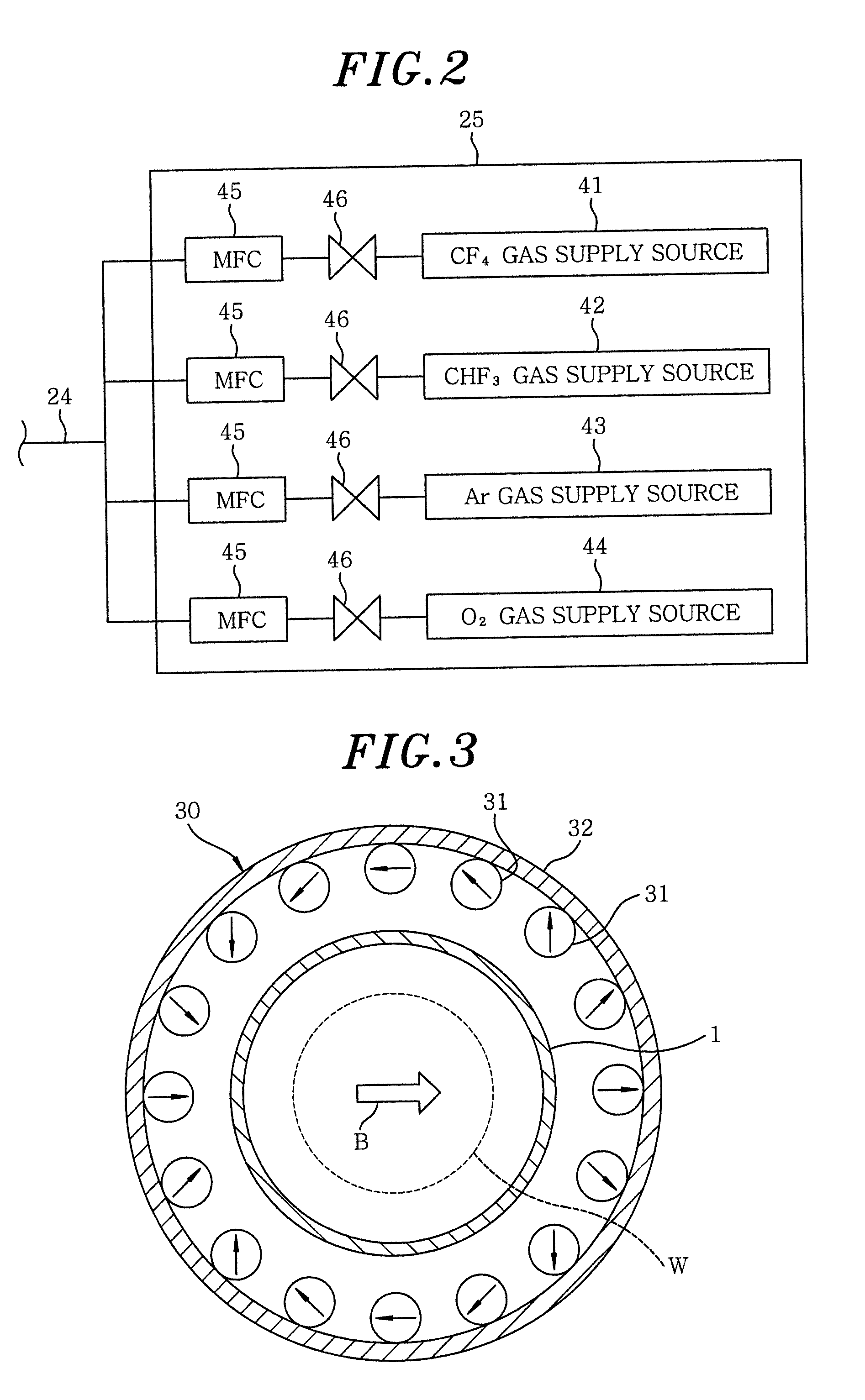
[0082] An etching was performed on the target object 110 of a laminated structure shown in FIG. 5 by using the plasma etching apparatus 100 and a gaseous mixture of CF4 / CHF3 / Ar / O2 as an etching gas, forming the recess 108 by using the resist film (PR) 107 as a mask. Herein, the resist film (PR) 107 was of a film thickness of 400 nm and was formed of a material including elements: C, H, F and O. The anti-reflection film (BARC) 106 was of a film thickness of 58 nm, the silicon nitride film (Si3N4 film) 105 was of a film thickness of 60 nm, and the polycrystalline silicon layer 104 was of a film thickness of 65 nm. Further, the line-and-space pattern of the resist film (PR) 107 was of a line width of 0.6 μm and a space width of 0.24 μm.

[0083] Etching conditions are described as follows:

[0084] CF4 / CHF3 / Ar / O2=20 / 25 / 300 / 10 mL / min (sccm)

[0085] Pressure=13.3 Pa (100 mTorr)

[0086] RF frequency (the high frequency power supply 15)=13.56 MHz

[0087] RF power=400 W (1.27 W / cm2)

[0088] Backsid...


PUM

PropertyMeasurementUnit
flow rateaaaaaaaaaa
flow rateaaaaaaaaaa
pressureaaaaaaaaaa

Abstract

A plasma etching method includes the step of: etching a silicon layer of a target object by using a plasma generated from a processing gas containing a fluorocarbon gas, a hydrofluorocarbon gas, a rare gas and an O2 gas and by employing a patterned resist film as a mask. The target object includes the silicon layer whose main component is silicon and the patterned resist film formed over the silicon layer.

Description

FIELD OF THE INVENTION [0001] The present invention relates to a plasma etching method including a process for etching a target object by using a plasma. BACKGROUND OF THE INVENTION [0002] In a manufacturing process of a semiconductor device, a process for etching a laminated film by using a mask such as a patterned resist film is repeatedly performed. For example, in a manufacturing process of a gate electrode, laminated on a semiconductor substrate in order from the bottom are a silicon oxide film or a silicon nitride film serving as a gate insulating film, a polycrystalline silicon layer serving as a gate electrode, a hard mask layer formed of silicon nitride or the like, an anti-reflection film formed of silicon oxide or the like, and a resist film. Further, the anti-reflection film and the hard mask layer are dry-etched by using the resist film patterned by employing a photolithography technique as a mask. After the resist film is removed by ashing, the polycrystalline silicon ...

Claims


Application Information

Patent Timeline
Patent Type & Authority Applications(United States)
IPC IPC(8): H01L21/306C23F1/00
CPCH01J2237/2001H01L21/3065H01L21/3081H01L21/32139H01L21/31144H01L21/32137H01L21/31116
Inventor KIKUCHI, AKIHIROTSUNODA, TAKASHISAKAMOTO, YUICHIRO
Owner TOKYO ELECTRON LTD
Why Eureka
Try Eureka