Electrode compositions and configurations for electrochemical bioreactor systems

a bioreactor and electrochemical technology, applied in the direction of electrochemical methods, diaphragms, water/sewage treatment, etc., can solve the problems of generally inapplicability of two-compartment fuel cells, and achieve the effect of enhancing the rate of electron transfer

Inactive Publication Date: 2007-12-27
MICHIGAN STATE UNIVESITY BOARD OF TRUSTEES OF
View PDF7 Cites 6 Cited by
  • Summary
  • Abstract
  • Description
  • Claims
  • Application Information

AI Technical Summary

Benefits of technology

[0020] It is therefore an advantage of the present invention to provide an electrochemical bioreactor system having improved electrodes that enhance the rate of electron transfer from cells.
[0021] It is another advantage of the present invention to provide an electrochemical bioreactor system having an improved electrode that has utility as an enzymatic fuel cell.
[0022] It is yet another advantage of the present invention to provide an electrochemical bioreactor system having an improved electrode that has utility as a sensor for succinate detection.
[0023] It is still another advantage of the present invention to provide an electrochemical bioreactor system having an improved electrode that has utility as an engineered catalyst for the synthesis of fumarate or succinate.
[0024] It is a further advantage of the present invention to provide an electrochemical bioreactor system having an improved electrode with an enzyme immobilization protocol to link nicotinamide adenine dinucleotide (NAD+), neutral red, and fumarate reductase to the electrode.
[0025] It is yet another advantage of the invention to provide a fuel cell system that can be used as either an enrichment device for electrophilic microorganisms; that is, those which use an electrode as an electron acceptor, or electron donor for energy conservation.

Problems solved by technology

Two compartment fuel cells are generally not practical because of the requirement for a ferricyanide solution and aeration in the cathode compartment.

Method used


Image

  • Electrode compositions and configurations for electrochemical bioreactor systems
  • Electrode compositions and configurations for electrochemical bioreactor systems
  • Electrode compositions and configurations for electrochemical bioreactor systems

Examples


example 1

Microbial Preparations and Measurements

[0059] Sewage sludge (i.e., a mixture of anaerobic bacteria) was obtained from the Jackson, Mich., USA, sewage treatment plant. The fresh anaerobic sludge was allowed to settle under an N2 atmosphere for 1 day to remove solid particles. The suspended cells were used as a catalyst and were maintained in an anaerobic bottle by adding glucose (5 g / L) once a week. The resting cells were harvested by centrifugation at 5,000×g at 4° C. and were washed twice and resuspended in anolyte medium 1. Anolyte medium I contained: 100 mM phosphate buffer (pH 7.0), 10 g / L sodium lactate, 5 g / L peptone and 5 g / L yeast extract. The initial concentration of sewage sludge cell suspension was adjusted to 5.5 mg / ml cell protein as determined (see, Park and Zeikus, “Utilization Of Electrically Reduced Neutral Red By Actinobacillus Succinogenes: Physiological Function Of Neutral Red In Membrane-Driven Fumarate Reduction And Energy Conservation”, J. Bacteriol. 1812:240...

example 2

Electrode Compositions

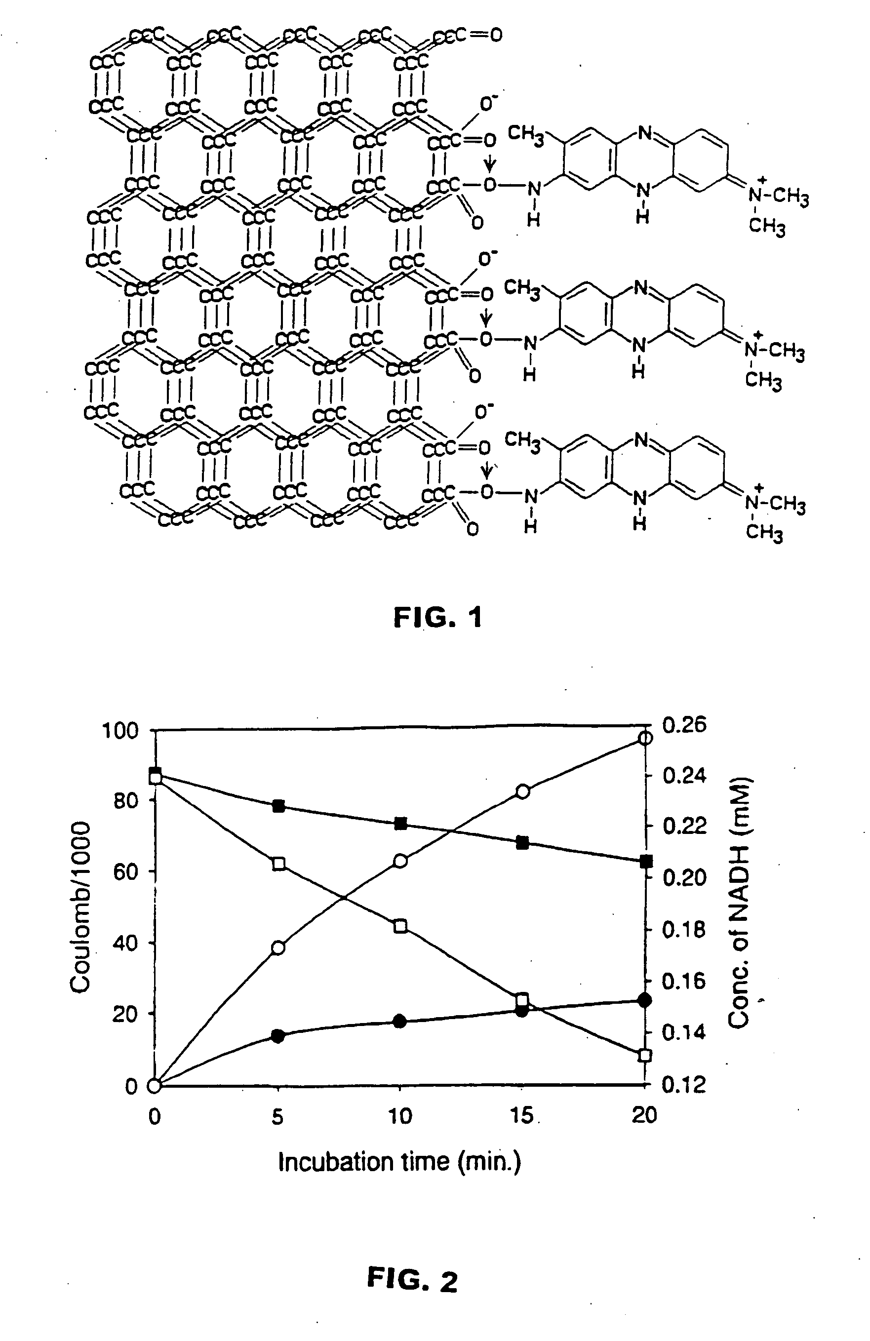
[0061] A procedure to covalently link neutral red to woven graphite felt was developed (see FIG. 1). The theoretical surface area of the woven graphite felt anode is 1.27 m2(2.7 g) versus a graphite plate anode with approximately 80 cm2. This procedure involved the following steps: (1.) cleaning the graphite felt electrode by soaking in methanol for 12 hours and then distilled water for 12 hours; (2.) drying the electrode at 120° C. for 1 hour; (3) making a carboxy surface by heating at 200° C. for 48 hours; (4) soaking the electrode in dicyclohexylcarbodimide solution (2 mg / ml chloroform) at 4° C. for 6 hours; (5) binding neutral red (100 μmol) to the electrode by incubating the dicyclohexylcarbodimide solution at 4° C. for 12 hours. The neutral red was immobilized to the electrode by this procedure and did not leach-out in water.

[0062] Several different metallic graphite electrodes were designed so as to compare their electron transfer efficiencies to neutr...

example 3

Fuel Cell Design and Operation

[0064] Two compartment cell fuel cells were prepared using the configuration described in Park and Zeikus, “Electricity Generation In Microbial Fuel Cells Using Neutral Red And An Electronophore”, Appl. Environ. Microbiol., 66:1292-1297, 2000, except for using the electrodes prepared in Example 2; and the cation selective membrane was replaced with a 50 mm by 2 mm thick porcelain septum made from 100% Kaolin as described above in Example 2. The two compartment fuel cell of Park and Zeikus, “Electricity Generation In Microbial Fuel Cells Using Neutral Red And An Electronophore”, Appl. Environ. Microbiol., 66:1292-1297, 2000 requires aeration and ferricyanide solution in the cathode compartment.

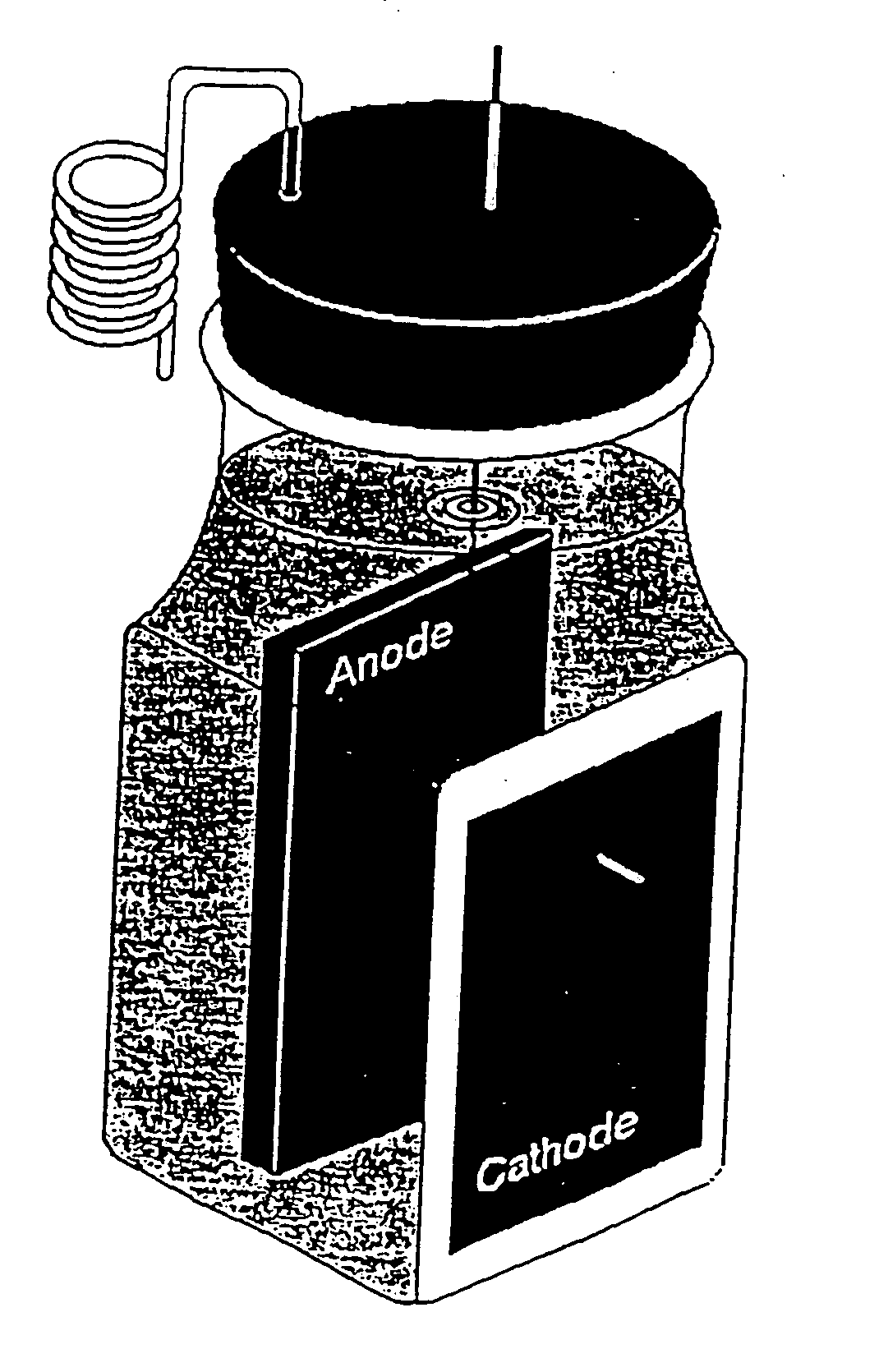
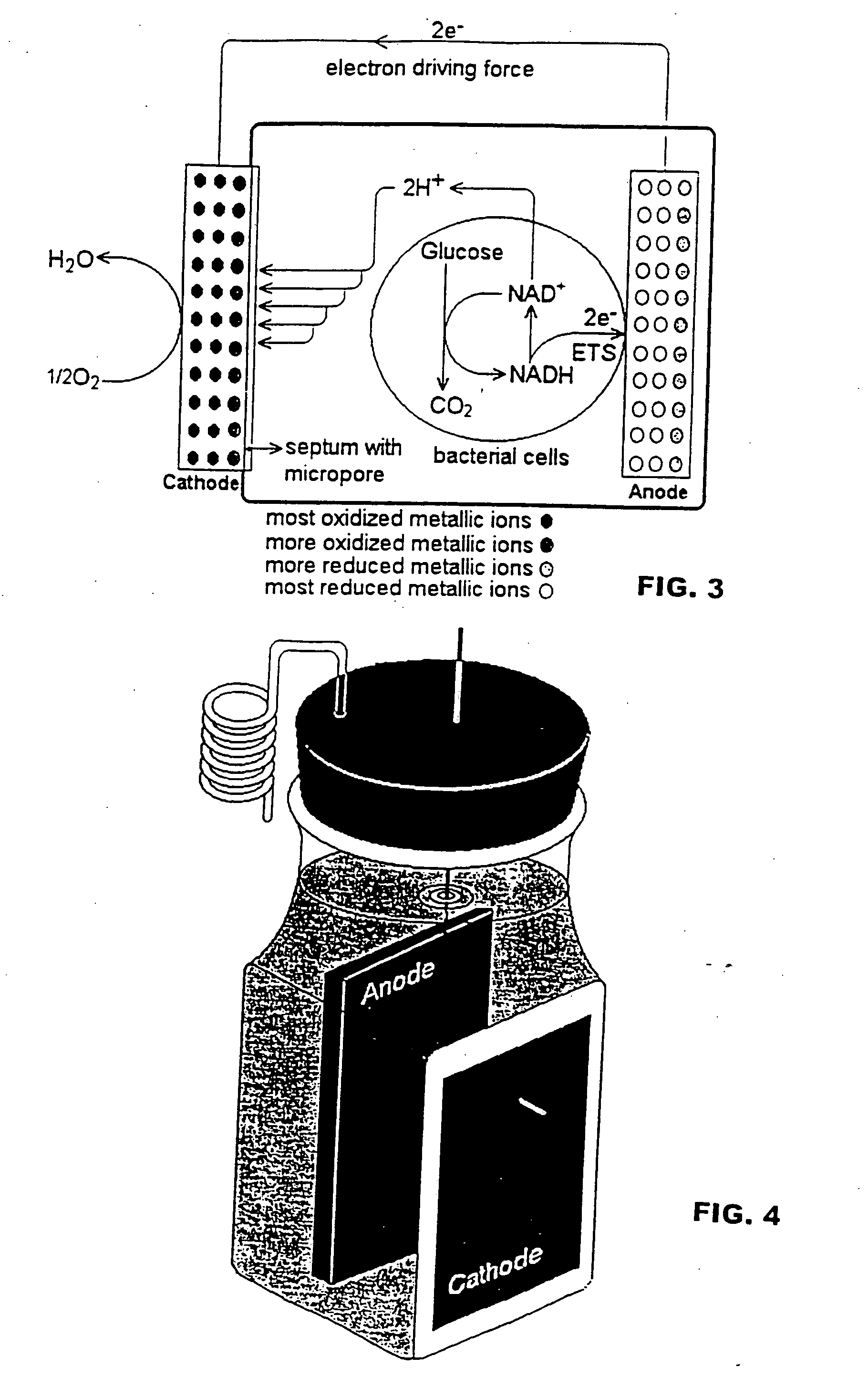
[0065] Because two compartment fuel cells are generally not practical because of the requirement for a ferricyanide solution and aeration in the cathode compartment, single compartment fuel cell design as shown in FIGS. 3 and 4 was prepared in order to eliminate ...


PUM

PropertyMeasurementUnit
total volumeaaaaaaaaaa
surface areaaaaaaaaaaa
pHaaaaaaaaaa

Abstract

Electrodes and configurations for electrochemical bioreactor systems that can use electrical energy as a source of reducing power in fermentation or enzymatic reactions and that can use electron mediators and a biocatalyst, such as cells or enzymes, to produce electricity are disclosed. Example electrodes in the system may comprise: (1) neutral red covalently bound to graphite felt; (2) a carboxylated cellulose bound to the graphite felt, neutral red bound to the carboxylated cellulose, NAD+ bound to the graphite felt, and an oxidoreductase (e.g., fumarate reductase) bound to the graphite felt; or (3) a metal ion electron mediator bound to graphite. Various biocatalysts, such as an oxidoreductase, cells of Actinobacillus succinogenes, cells of Escherichia coli, and sewage sludge, are suitable for use in the electrochemical bioreactor system.

Description

CROSS-REFERENCES TO RELATED APPLICATIONS [0001] This application claims the benefit of U.S. Provisional Patent Application No. 60 / 294,943 filed May 31, 2001, U.S. Provisional Patent Application No. 60 / 338,245 filed Nov. 8, 2001 and U.S. Provisional Patent Application No. 60 / 353,037 filed Jan. 30, 2002.STATEMENT REGARDING FEDERALLY SPONSORED RESEARCH [0002] Not Applicable. BACKGROUND OF THE INVENTION [0003] 1. Field of the Invention [0004] This invention relates to electrochemical bioreactor systems that can provide electrical enhancement of chemical synthesis and / or fermentations and / or biotransformations when supplied with electricity, that can generate electrical current detectable at a load, and that may used in chemical or biochemical sensing devices. In particular, the invention relates to improved electrodes for electrochemical bioreactor systems that can use electrical energy as a source of reducing power in fermentation or enzymatic reactions and that can use electron mediat...

Claims


Application Information

Patent Timeline
Patent Type & Authority Applications(United States)
IPC IPC(8): C12M1/18C12P1/00C12P13/00H01M8/16C02F1/46C02F1/461C12M1/40C12P7/46C12Q1/00C12Q1/02C12Q1/26
CPCC02F3/005C02F2001/46133C12P1/00C12P7/46C12Q1/004C12Q1/02Y10S436/806G01N2333/245G01N2333/32H01M8/16Y02E60/527Y10S435/817C12Q1/26Y02E60/50
Inventor ZEIKUS, JOSEPH GREGORYPARK, DOO HYUN
Owner MICHIGAN STATE UNIVESITY BOARD OF TRUSTEES OF
Why Eureka
Try Eureka