Bidirectional data repeater switch

a repeater switch and data bus technology, applied in the direction of logic circuit coupling/interface arrangement, pulse technique, frequency-division multiplex, etc., can solve the problems of slowing down the transition, high voltage on the bus, and increasing the cumulative parasitic capacitance on the bus

Active Publication Date: 2008-01-03
TEXAS INSTR INC
View PDF3 Cites 11 Cited by
  • Summary
  • Abstract
  • Description
  • Claims
  • Application Information

AI Technical Summary

Problems solved by technology

During a logic “high”, the active pulldown is off, and the passive pullup on the bus causes a high voltage on the bus.
The cumulative parasitic capacitance on the bus increases as more devices are added to the bus and as the bus length increases, further slowing transitions.
The non-zero on resi...

Method used


Image

  • Bidirectional data repeater switch
  • Bidirectional data repeater switch
  • Bidirectional data repeater switch

Examples


Embodiment Construction

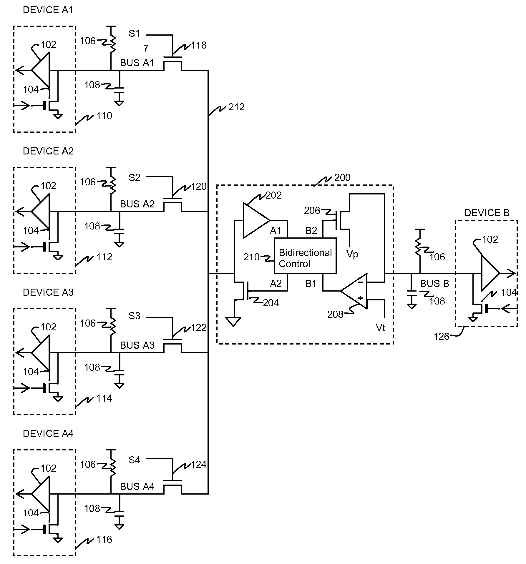
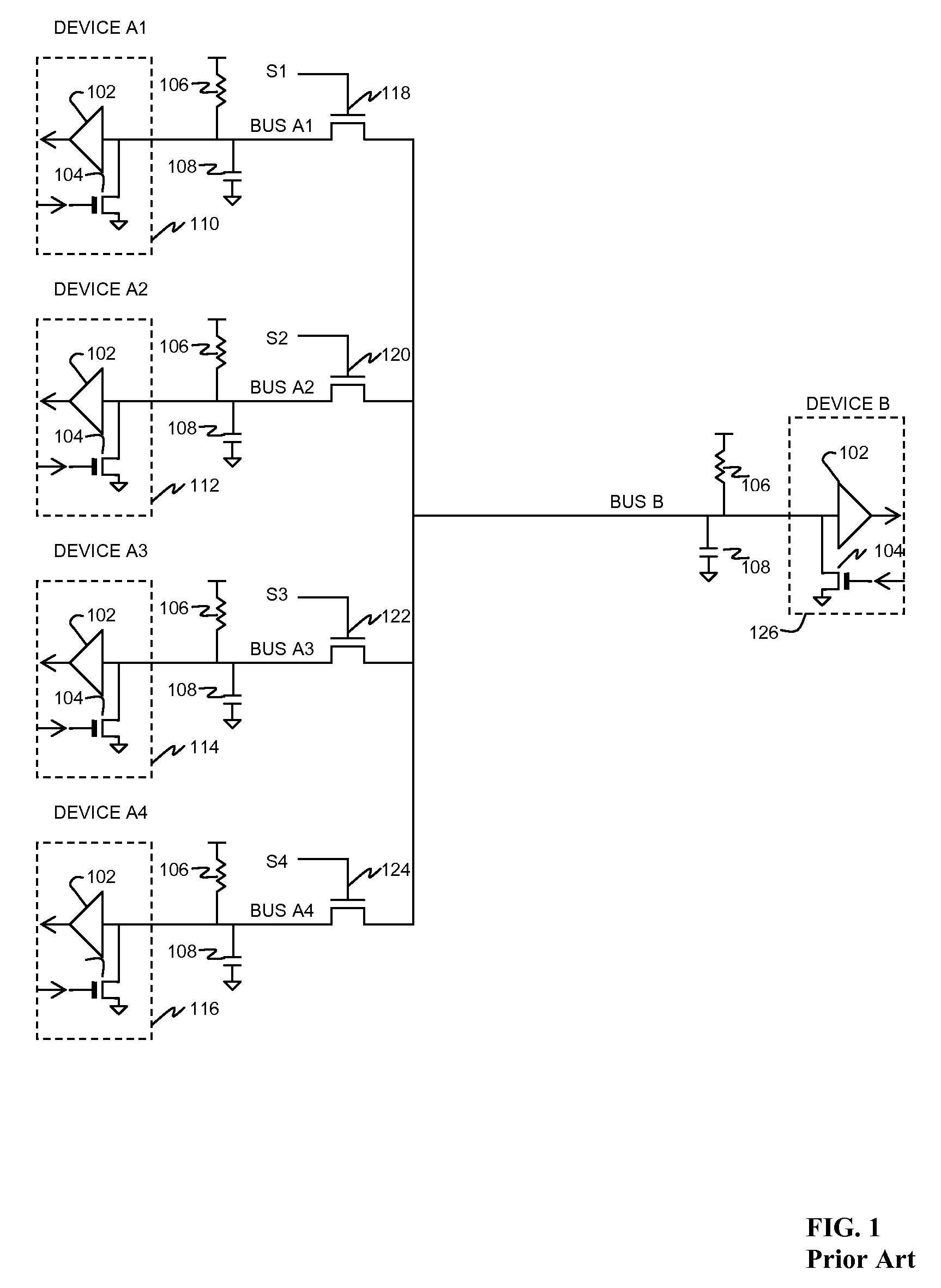
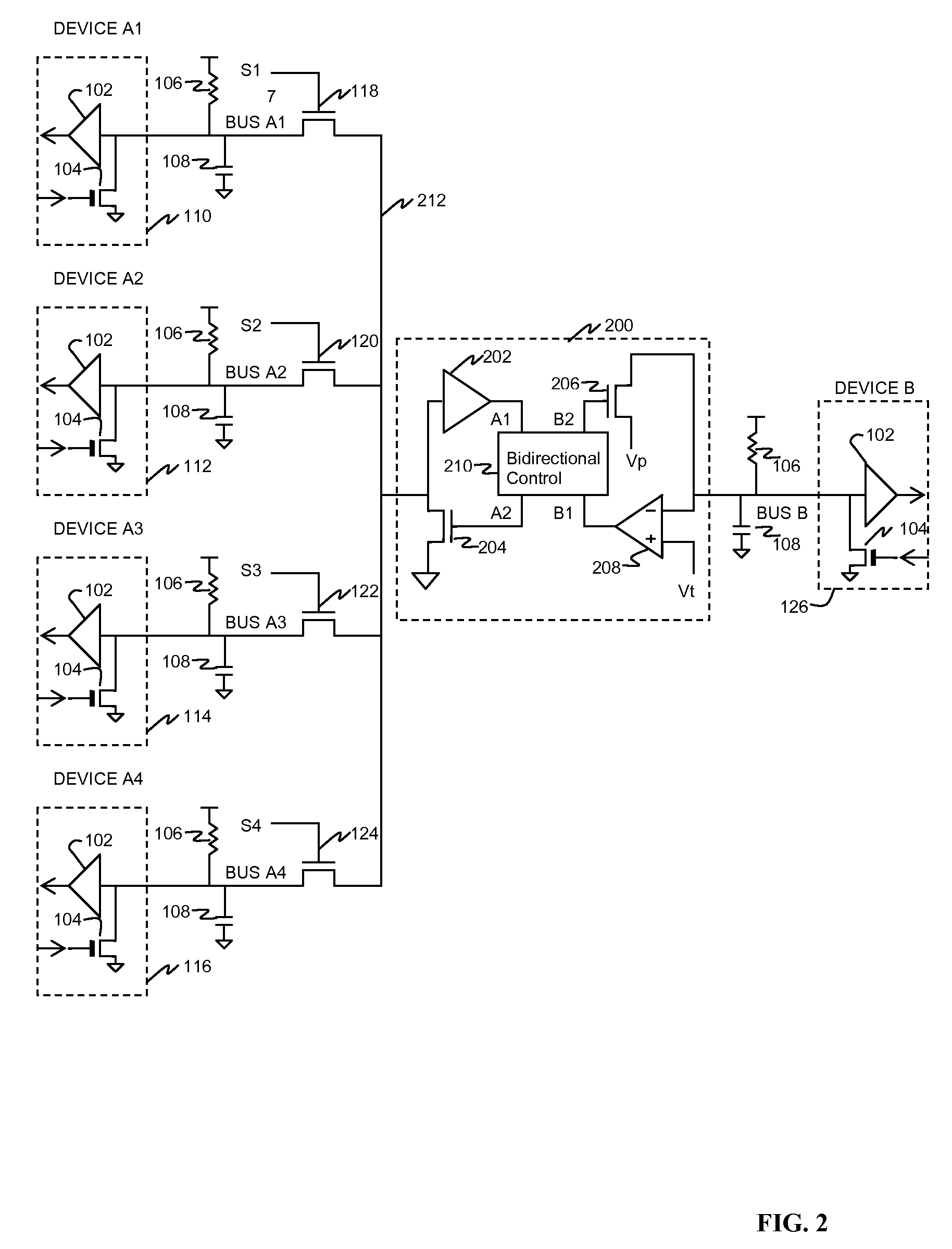
[0023]In FIG. 1 (prior art), a plurality of devices A1, A2, . . . , An, shown as devices 110, 112, 114, 116, couple data to and from respective buses A1, A2, . . . , An to a common bus B and hence to device 126. In each device a comparator 102, with threshold set at an appropriate level typically midway between logic “high” and logic “low” voltages, has its input coupled to the respective A bus. An active pulldown 104 has its gate coupled to the data input of the device, and causes the bus to be pulled to a low voltage (typically ground) when the input transmit data line is high (while not shown, typically an inverter is placed in the line driving the gate of each active pulldown to compensate for the data inversion which otherwise takes place). The on resistance of active pulldown 104 is typically much lower than the passive pullup 106 so as to provide as low a logic “low” voltage as practical. Passive pullup 106 applies a logic “high” voltage to the bus when active pulldown 104 is...


PUM


Abstract

A bidirectional repeater and data multiplexer for serial data comprises a plurality of comparators 302, 304, 306, 308 coupled to the respective input/output (I/O) terminals of a plurality of serial data transceiver devices A1, A2, A3, A4 such as used in I2C communication. Also coupled to these I/O terminals is a plurality of active pulldowns 316, 318, 320, 322. The outputs of the comparators are coupled to N:1 Select 310 logic wherein the desired data input is selected responsive to select lines S1, S2, S3, S4. The output of the N:1 select logic is coupled to a bidirectional control circuit 210, which couples the selected data to the control terminal of an active pulldown 206 having its source coupled to a pulldown voltage Vp low enough to represent a logic “low” level but non-zero, and a drain connected to the I/O terminal of a device B. Also connected to the I/O terminal of device B is an inverting comparator having a threshold voltage Vt somewhat below the pulldown voltage Vp described above, such that the comparator ignores the low level Vp of the active pulldown, but responds to the less than Vp data zero level from device B. This prevents data lockup where data from An would flow back to the same device An. The data output of comparator 208 is thus a repeated version of data present on the I/O terminal of device B, and is coupled through 1:N Select 312 logic, responsive to the same select lines S1 . . . described above, to one of the plurality of active pulldowns 316, 318, 320, 322. Data from device An, one of the plurality of devices A1 . . . A4, is thus repeated and selectively routed to device B. Similarly, data from device B is selectively routed to the active pulldown coupled to the same device An. Pulldown voltages Vp and threshold voltages Vt may be varied to optimize coupling with device B, as long as the pulldown voltage Vp remains above the threshold voltage Vt; the pulldown and threshold voltages may be selected from a plurality of such pulldown and threshold voltages, in order to optimize noise margins when coupling to devices having different Vil and Vol specifications.

Description

[0001]This application claims priority, under 35 U.S.C. § 119(e)(1), of U.S. Provisional Application No. 60 / 747,105, entitled “Bidirectional Data Repeater Switch,” and having as its inventors Julie Hwang, Woo J. Kim, Alan S. Bass and Mark W. Morgan, filed May 12, 2006, and hereby incorporated herein by this reference.BACKGROUND OF THE INVENTION[0002]1. Field of the Invention[0003]This invention relates generally to bidirectional serial data buses, and more specifically to bidirectional repeating, switching, and multiplexing of data signals on a serial bus without the need for pass-gates.[0004]2. Description of the Related Art[0005]A commonly used bidirectional serial data bus used for inter-integrated circuit communication is known as 12C. Each device transmitting and / or receiving data to or from the bus has an input / output (I / O) terminal coupled to a line of the data bus. Within a first such device, the I / O terminal is coupled to the drain or collector of an active pulldown transis...

Claims


Application Information

Patent Timeline
IPC IPC(8): H03K19/003
CPCH03K19/0185
Inventor HWANG, JULIE A.KIM, WOO JINBASS, ALAN S.MORGAN, MARK W.
Owner TEXAS INSTR INC
Why Eureka
Try Eureka