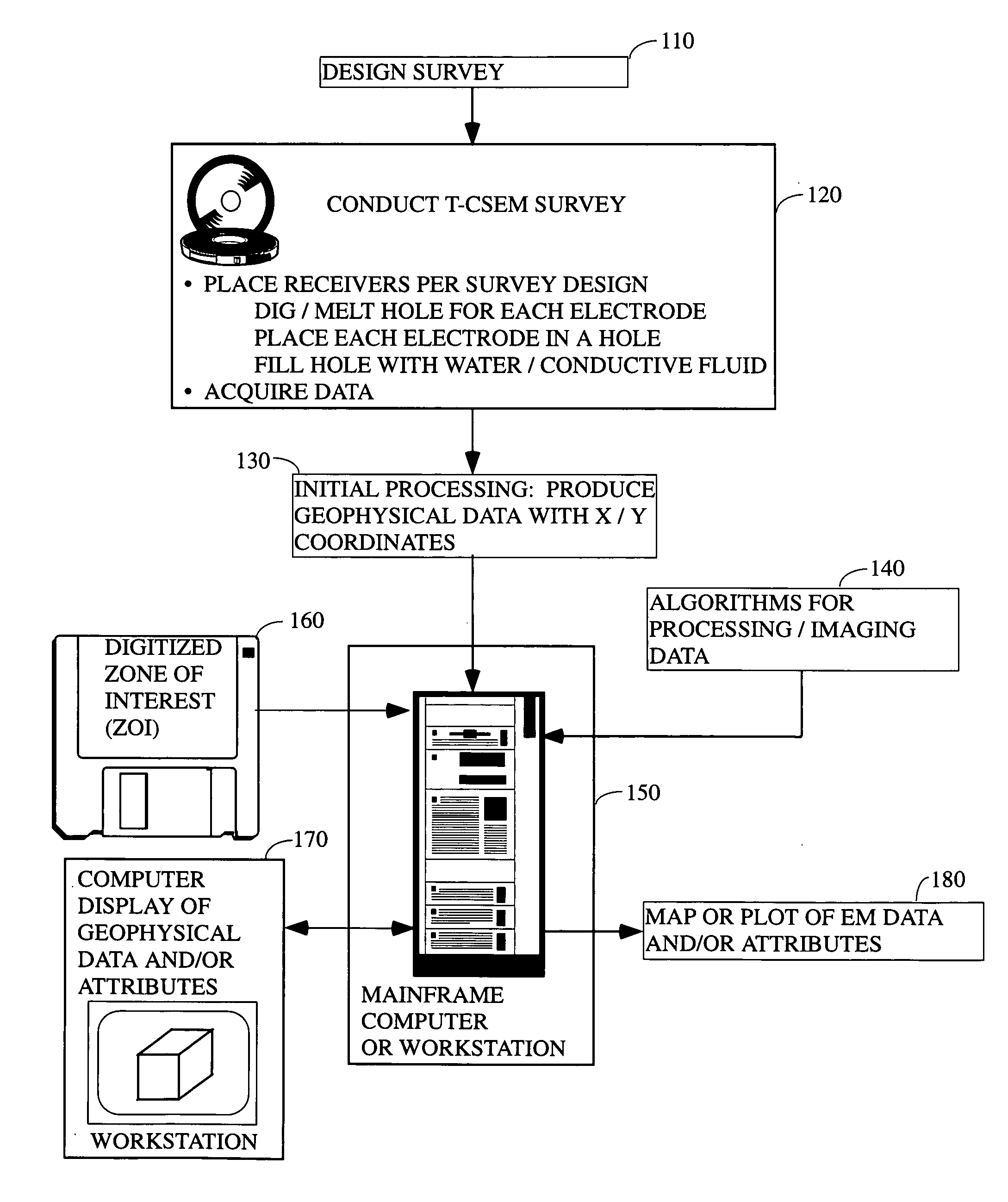
[0018] According to a preferred aspect of the instant invention, there is provided a
system and method of collecting CSEM data (and especially t-CSEM data), which permits effective exploration, appraisal, development, and surveillance of hydrocarbon reservoirs in polar regions by providing improved ground coupling between the electrodes, the surficial ice, the sub-
ice water, and hence, to the earth itself. As a consequence, a higher quality transmitted and received
signal is obtained, and through the use of the methods taught herein, CSEM becomes feasible for use in hydrocarbon detection in such regions.
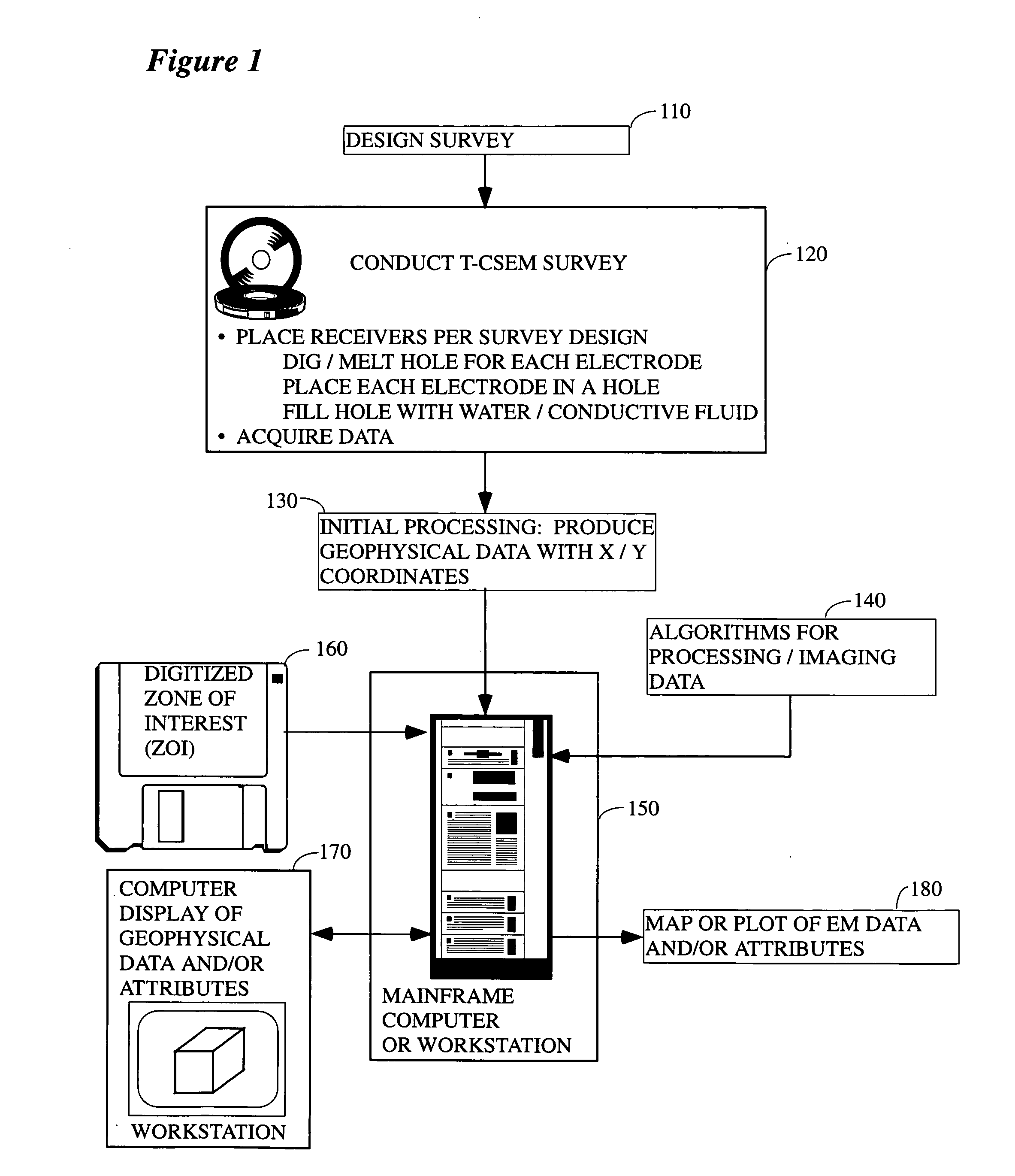
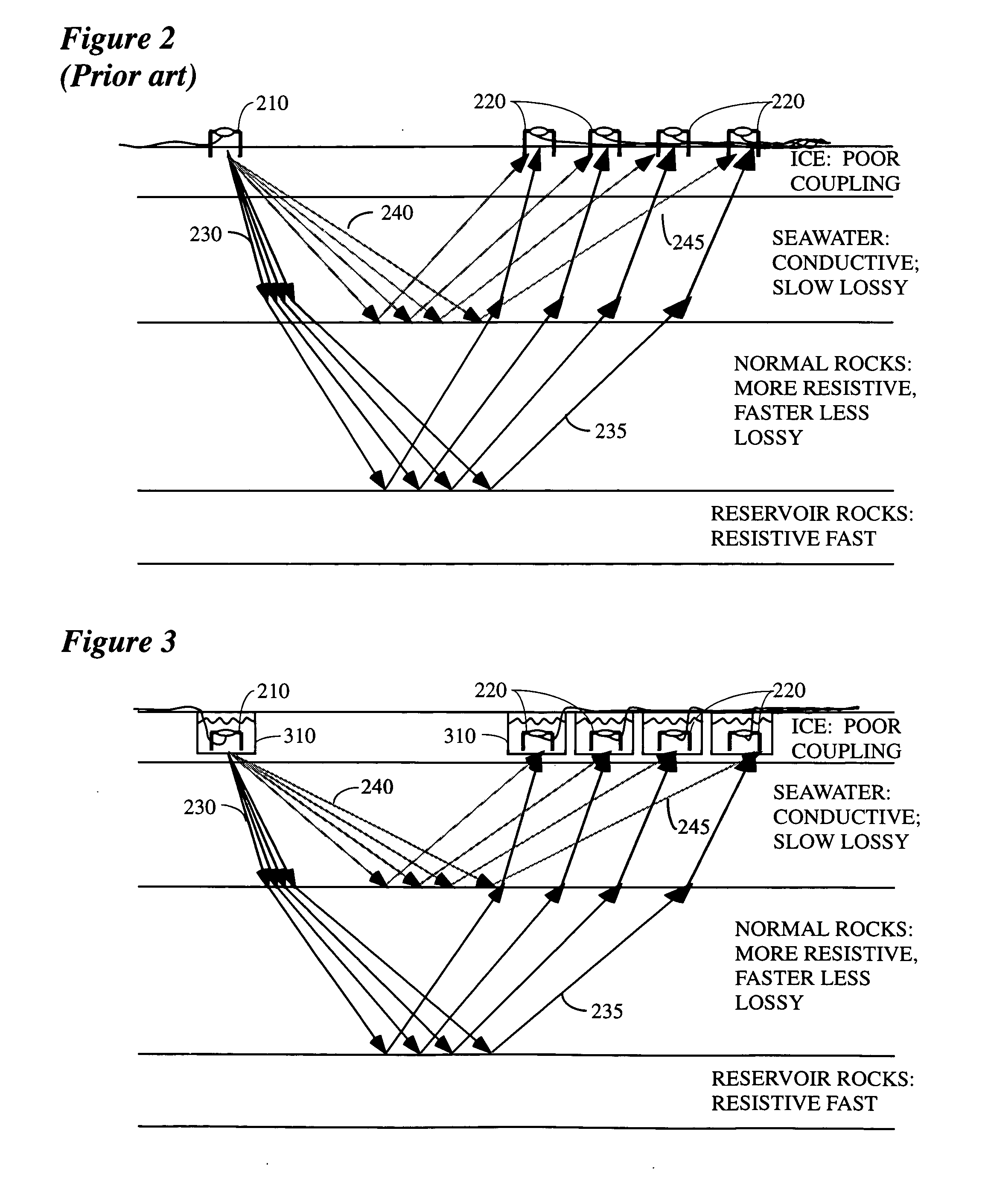
[0022] Note that this approach makes it possible for the first time to collect high quality EM data in a marine setting by using modified land techniques. That is, one aspect of the instant invention involves conducting a CSEM survey on the pack ice floating on water (fresh- or salt-water). Obviously, if the weather were warmer, and the ice were melted, a conventional or unconventional marine survey could be conducted (e.g., as is generally indicated in FIG. 5). However, in polar regions the season of
open water is short or absent, so that these marine techniques have limited applicability. However, when the body of water (or at least a portion of it) freezes over, a land-style survey may be conducted instead on the resulting ice layer. In the case of marine surface ice, the
electrode holes may easily penetrate the floating ice, reaching the unfrozen
seawater below (which has excellent
conductivity), and avoiding altogether those problems caused by the poor
conductivity of ice. In this marine case, the data are analyzed by means described elsewhere, perhaps taking special steps to account for reflection from the seafloor.
[0023] In another variation, there is provided a method of EM exploration in polar regions that may be covered by tundra, or by swamps, or by wide shallow rivers which are ecologically fragile, particularly during warmer seasons. Those of ordinary skill in the art will recognize that the only practical time to enter such areas with men and equipment is during the colder seasons, when the surface is stabilized by ice and
snow-cover. During that season
seismic exploration is feasible, but logistically difficult, because the
cold weather causes
mechanical devices (e.g. vibrators) to fail more often than in warmer weather. Further, obtaining high quality coupling of seismic geophones to the ground during this time is problematic. Also, seismic sampling requirements are more stringent than are EM sampling requirements (since the seismic wavelengths are shorter than the EM wavelengths, in typical practice), so that many more source-locations and
receiver-locations are required for seismic surveying than for CSEM surveying. According to the instant invention there is provided a CSEM surveying method substantially as described above, but wherein the ground coupling is improved by digging or drilling holes into the tundra or ice into which the electrodes are thereafter placed. Note that through the use of the present invention, CSEM in such environments can serve to identify areas that are likely to contain hydrocarbons in the subsurface, making it possible to high-grade those particular areas for subsequent seismic surveys that are more suitable for obtaining high-resolution seismic images of those reservoirs.
[0024] In another variation, in a survey conducted on ice or
snow,
magnetic energy is injected into the ice, via current loops deployed over the ice, and received (via surface and subsurface propagation paths) at current loops similarly deployed, at a range of distances from the sources. This sort of survey is particularly useful at finding conductive anomalies, rather than resistive anomalies (hydrocarbons). Nevertheless, the present invention can be utilized to conduct such a conventional land-based
magnetic survey on top of floating ice during
cold weather. Compared to conventional marine CSEM surveying (with sources and receivers near the sea-floor), a marine survey conducted as described above requires that the EM energy signal from the subsurface propagates additionally through the
water layer, twice (down and up). This means that the current invention will be more useful in shallow waters than in deep waters, although with sufficiently powerful sources and sufficiently sensitive receivers, the depths can be extended. Modeling shows that sea-water of 100 m depth causes no serious problems.
[0025] In summary, the present inventors have discovered that a critical feature of the marine environment, which makes conventional CSEM practical in that setting, is the intimate and uniform coupling of sources and receivers to the medium (
seawater). Those skilled in the art of marine CSEM will realize that
deep water (relative to target depth) is also important to the practicality of f-CSEM, but that this restriction does not apply to t-CSEM. As is disclosed herein, the present inventors have realized that this coupling-principle can also be realized in polar environments, because of the ubiquity in such environments of ice and
snow. This is a key aspect of the present invention, i.e., the realization that according to the techniques taught herein ice provides for good coupling in polar environments in the same fashion as water provides same in marine environments, thereby making it possible to collect high quality CSEM data. In particular, the techniques taught herein enable the collection of high-quality, CSEM data, suitable for exploration for the deep resistivity anomalies characteristic of hydrocarbon reservoirs.

