Lab-On-A-Chip For An On-The-Spot Analysis And Signal Detection Methods For The Same

a biosensor and signal detection technology, applied in the field of labonachip version of biosensors, can solve the problems of low reproducibility of analysis, inability to hold the samples in a precise arrangement, and frequent application of severe pain, and achieve the effect of reducing costs

Inactive Publication Date: 2008-01-24
BIODIGIT LAB CORP
View PDF2 Cites 54 Cited by
  • Summary
  • Abstract
  • Description
  • Claims
  • Application Information

AI Technical Summary

Benefits of technology

[0035] For illustrating the utility of the lab-on-a-chip proposed in this invention, a POCT version of ELISA is developed by employing the method of cross-flow chromatography (References: J. H. Cho et al., 2005, Anal. Chem., Vol. 77, page 4091-4097). This would demonstrate a widespread application of immunosensors to various analytes with minimal costs and, potentially, dimensions. The concept was originally developed to use enzymes as signal generators in immuno-chromatographic assay by sequentially accomplishing antigen-antibody bindings and catalytic reactions to generate signals. A lab-on-a-chip is constructed in this invention to achieve a semi-automatic switching of the sequential processes for a complete analysis and a miniaturization of the immunosensor. This chip is fabricated as stated above by incorporating a conventional immuno-strip into a plastic chip with elaborately devised channels on the surfaces.

Problems solved by technology

Despite their simplicity in use, one of the major drawbacks in routine, frequent application has been the induction of severe pain, in the case of using whole blood for specimens, because of a large amount of sampling.
To reduce the sample size, membrane pads can typically be cut smaller than 4 mm in width, which would make it difficult to hold them in a precise arrangement.
This causes a low reproducibility of analysis and inaccuracy in detection.
However, since the present status of this technology remains undeveloped in some aspects, such as reproducibility in mass production of the chip, the time of its practical application appears considerably delayed (References: O. A. Schueller et al., 1999, Sens. Acuat. A, Vol. 72, page 125-139).

Method used


Image

  • Lab-On-A-Chip For An On-The-Spot Analysis And Signal Detection Methods For The Same
  • Lab-On-A-Chip For An On-The-Spot Analysis And Signal Detection Methods For The Same
  • Lab-On-A-Chip For An On-The-Spot Analysis And Signal Detection Methods For The Same

Examples


example 1

Synthesis of HRP-Labeled Antibody

1-1. Production of Monoclonal Antibody

[0079] A monoclonal antibody specific to cTnI was raised through the adoption of a standard protocol. cTnI (30 g) was emulsified with Complete Freund's adjuvant and injected into the peritoneal cavity of a 6-week old Balb / c mouse. After 3 weeks, the mouse was immunized with the same amount of cTnI emulsified with Incomplete Freund's adjuvant. An identical procedure was repeated 2 weeks later, and the final immunization was conducted after the same period with cTnI dissolved in 10 mM phosphate buffer, pH 7.4, (PB) containing 140 mM NaCl (PBS). Three days after the final boosting, the mouse splenocytes were collected and fused with murine plasmacytoma (sp2 / 0 Ag 14) as a fusion partner. Fused hybridoma cells were screened based on HAT selection, and a cell clone producing antibody specific to cTnI (BD Clone 12) was finally screened by immunoassay using antigen-coated microtiter plates. This antibody was produced ...

example 2

Construction of Lab-on-a-Chip

2-1. Preparation of Immuno-Strip

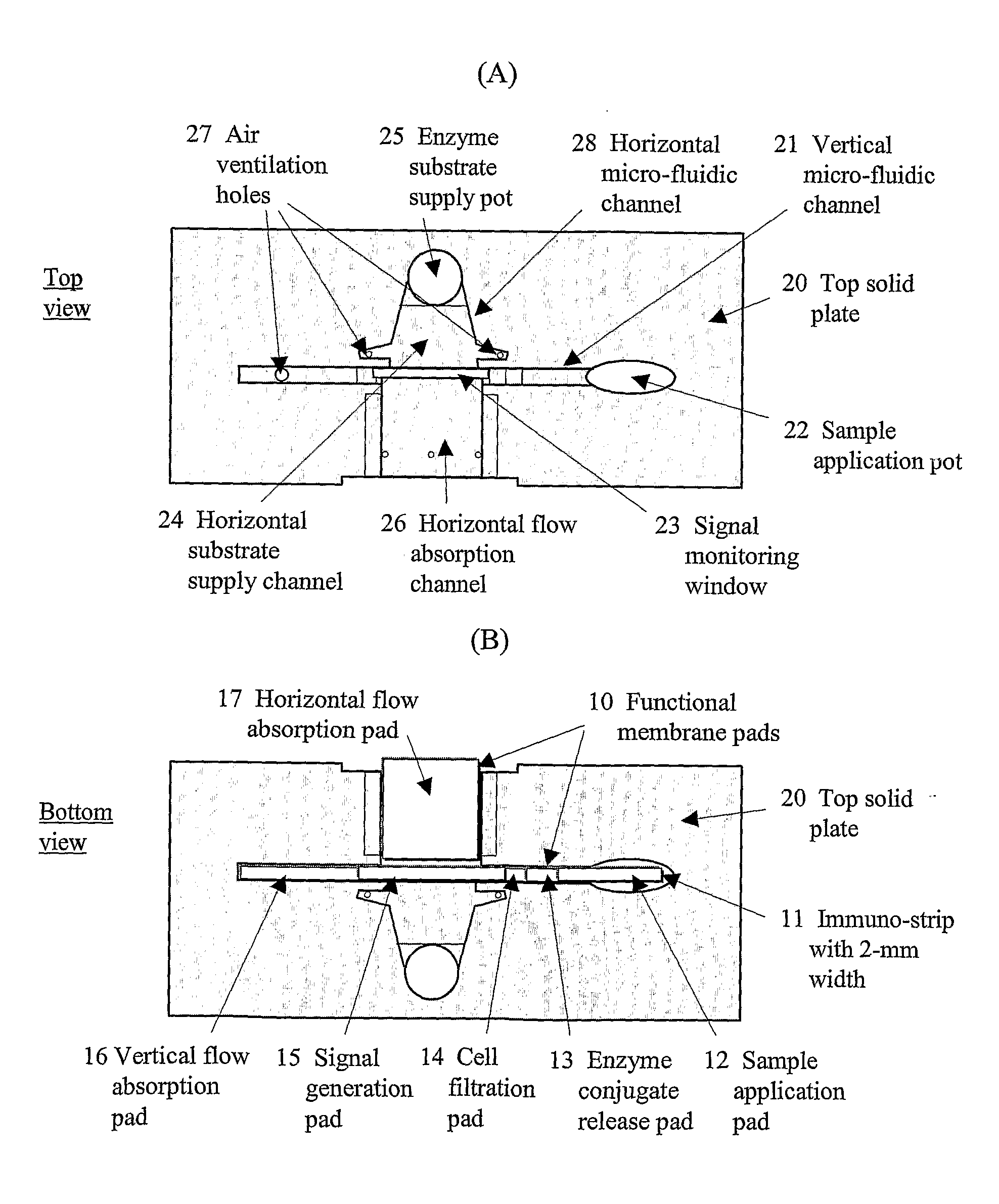
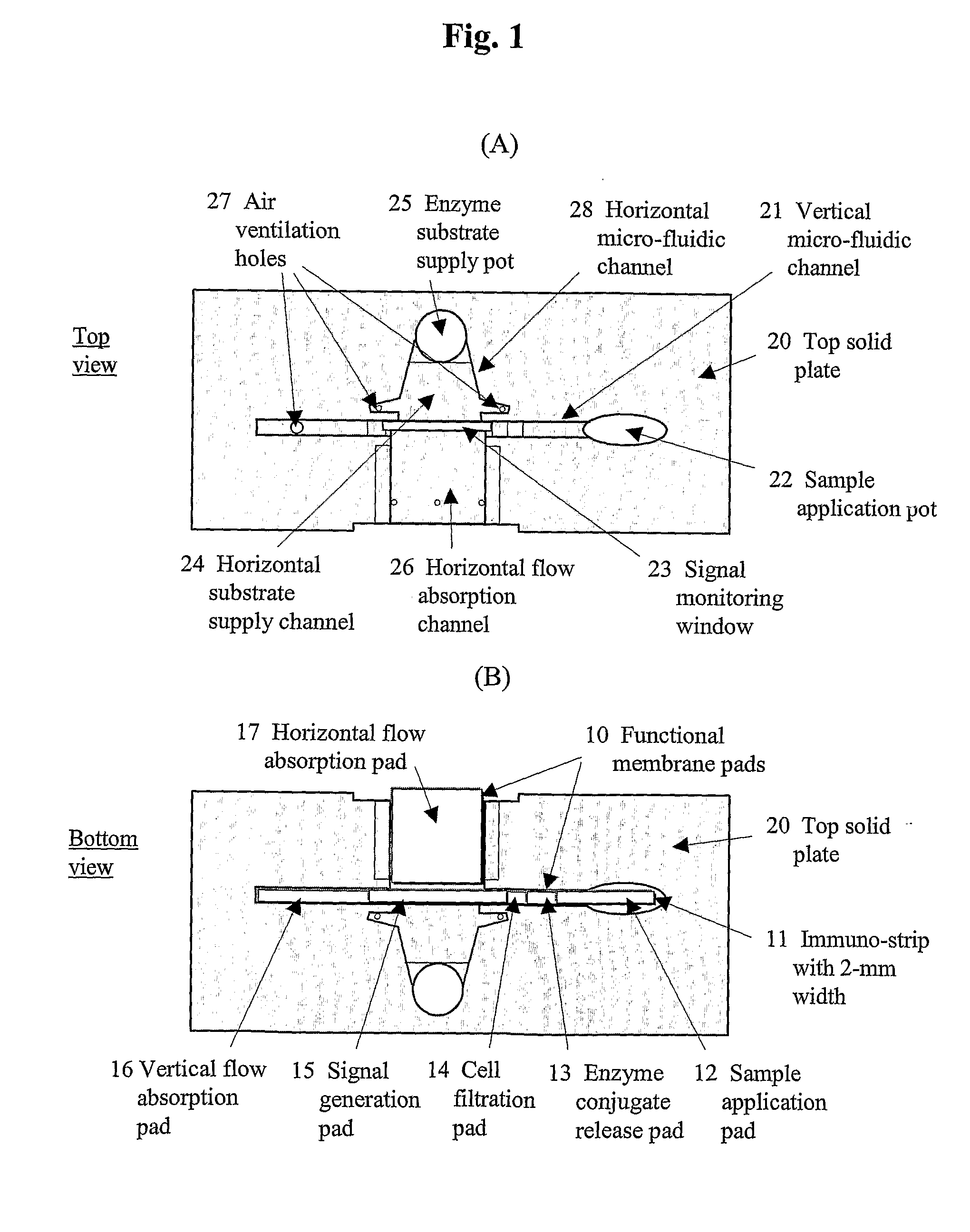
[0081] To accomplish the immuno-chromatographic assay for cTnI in the vertical direction, four different functional membrane pads have been employed (refer to FIG. 1B). Each sample application pad was a glass fiber membrane (2×15 mm; Ahlstrom 8980) pre-treated with polyvinyl alcohol by the manufacturer. A conjugate release pad was fabricated by transferring 8 L of a conjugate solution onto a glass membrane (2×5 mm; Rapid 24Q). The conjugate solution was prepared by diluting the HRP labeled-antibody (2.5 g / mL) with 100 mM PB containing 0.5% casein (Casein-PB), HAMA blocker (150 g / mL), ascorbic acid (5 mM), Triton X-100 (0.5%, v / v), and trehalose (20%, w / v). A signal generation pad was made by dispensing (1.5 L / cm) the monoclonal antibody (Clone 19C7; 2 mg / mL) in PBS onto a site at 10 mm from the bottom of NC membrane (2×25 mm) using a microdispenser (BioJet 3000, Biodot, Irvine, Calif.). On the same membrane, goat anti-m...

example 3

Characterization of Analytical Performances

3-1. Preparation of Standard Samples of cTnI

[0085] A stock of cTnI (1 mg / mL; I-T-C complex form) was serially diluted with human serum to prepare samples at pre-determined concentrations. The serum itself was regarded as the negative sample.

3-2. Calibration

[0086] Under optimal conditions, the responses of the lab-on-a-chip to the analyte concentrations were obtained using the standard samples of cTnI. The samples were added into different lab-on-a-chip, the immune reactions were processed for 15 min and, sequentially, the signal generation was processed for 5 min after the enzyme substrate was supplied. The chip with colored signals as shown in FIG. 2 was placed under a digital camera (FA185A#ABA, Hewlett-Packard, Palo Alto, Calif.) built within a detector and illuminated from the bottom using a light source (SR0307A-5230, Seho Robot, South Korea) as shown in FIG. 3. The image of the signal generation pad was captured and the color de...


PUM

PropertyMeasurementUnit
widthaaaaaaaaaa
volumeaaaaaaaaaa
widthsaaaaaaaaaa

Abstract

The present invention relates to a lab-on-a-chip version of biosensor for an on-the-spot analysis whose analytical performances were remarkably improved, by incorporating commercial membranes, traditionally used for rapid diagnostics, into microfluidic channels engraved on the surface of a plastic chip, as follows: 1) reduction of sample size; 2) realization of variable functions for total analysis; and 3) transfer of medium by capillary action without the assistance of an external force.

Description

TECHNICAL FIELD [0001] The present invention relates to a lab-on-a-chip version of biosensor for an on-the-spot analysis whose analytical performances were remarkably improved, by incorporating commercial membranes, traditionally used for rapid diagnostics, into microfluidic channels engraved on the surface of a plastic chip, as follows: 1) reduction of sample size; 2) realization of variable functions for total analysis; and 3) transfer of medium by capillary action without the assistance of an external force. BACKGROUND ART [0002] Rapid analytical devices based on chromatography using the lateral flow of medium through micro-pores present within the matrices of membrane pads have been conventionally applied for the diagnoses of various diseases and symptoms (References: S. H. Paek et al., 2000, Methods, Vol. 22, page 53-60; S. H. Paek et al., 1999, Biotechnol. Bioeng., Vol. 62, page 145-153; Y Kasahara et al., 1997, Clin. Chimi. Acta, Vol. 267, page 87-102). Despite their simplici...

Claims


Application Information

Patent Timeline
Patent Type & Authority Applications(United States)
IPC IPC(8): G01N21/78B01J19/00
CPCB01L3/502707B01L3/50273B01L2300/0627B01L2300/0645G01N33/54366B01L2300/0825B01L2300/0887B01L2400/0406B01L2300/0681B01L3/5023B01L3/502715B01L2200/10
Inventor PAEK, SE-HWANKIM, JOO-EUN
Owner BIODIGIT LAB CORP
Why Eureka
Try Eureka