Negative electrode for lithium ion secondary battery, method for producing the same, and lithium ion secondary battery

a secondary battery and negative electrode technology, applied in the field of lithium ion secondary batteries, can solve the problems of difficult even for a metal capable of being alloyed with silicon

Active Publication Date: 2008-01-24
PANASONIC CORP
View PDF2 Cites 82 Cited by
  • Summary
  • Abstract
  • Description
  • Claims
  • Application Information

AI Technical Summary

Benefits of technology

[0012] The present invention relates to a negative electrode for a lithium ion secondary battery, including a current collector, an intermediate layer formed on a surface of the current collector, and an active material layer formed on the intermediate layer. The current collector comprises a metal capable of being alloyed with silicon. The active material layer comprises an active material comprising silicon. The intermediate layer includes silicon and oxygen and prevents the metal capable of being alloyed with silicon from diffusing into the active material layer.
[0013] By forming the intermediate layer between the current collector and the active material layer, the constituent element of the current collector can be prevented from diffusing into the active material layer. The reason why the intermediate layer including silicon and oxygen can prevent the diffusion of the constituent element of the current collector is not yet clear, but it is probably as follows.
[0014] In the intermediate layer including silicon and oxygen, the silicon and the oxygen are strongly bound together by covalent bonding. In order for the constituent element of the current collector to diffuse through the intermediate layer, the constituent element of the current collector needs to cut the bond between the silicon and the oxygen and combine with the silicon. However, it is difficult even for a metal capable of being alloyed with silicon (e.g., copper or nickel) to cut the bond between the silicon and the oxygen and combine with the silicon. Thus, by interposing the intermediate layer including silicon and oxygen between the current collector and the active material layer, the diffusion of the constituent element of the current collector into the active material layer is suppressed.
[0018] According to these methods, it is possible to enhance the production efficiency of negative electrodes for lithium ion secondary batteries. For example, it is possible to select a production condition in which the deposition speed is heightened to form an active material layer in a short time. It is also possible to select a high-temperature and short-time condition for heat treatment that is performed to remove moisture on the surface of the active material layer formed.
[0019] By forming the intermediate layer between the current collector and the active material layer, the diffusion of the constituent element of the current collector into the active material layer can be suppressed. Hence, in an aspect of the invention, the current collector does not become so brittle and the adhesion of the active material layer to the current collector is sufficiently maintained. It is therefore possible to provide a lithium ion secondary battery with good cycle characteristics.
[0020] The intermediate layer includes silicon just like the active material layer. That is, the intermediate layer is capable of absorbing and desorbing lithium and functions as an active material. Thus, in an aspect of the invention, even if the intermediate layer is formed, the energy density of the negative electrode does not decrease, which makes it possible to provide a lithium ion secondary battery with a high capacity. Also, since the intermediate layer includes silicon just like the active material layer, the production process can be simplified and the production efficiency can also be improved. It therefore becomes possible to produce a negative electrode at low costs.

Problems solved by technology

However, it is difficult even for a metal capable of being alloyed with silicon (e.g., copper or nickel) to cut the bond between the silicon and the oxygen and combine with the silicon.

Method used


Image

  • Negative electrode for lithium ion secondary battery, method for producing the same, and lithium ion secondary battery
  • Negative electrode for lithium ion secondary battery, method for producing the same, and lithium ion secondary battery
  • Negative electrode for lithium ion secondary battery, method for producing the same, and lithium ion secondary battery

Examples


example 1

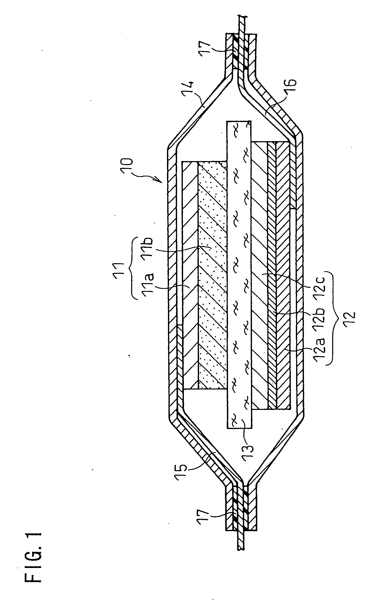
[0092] A layered-type lithium ion secondary battery as illustrated in FIG. 1 was produced.

(i) Preparation of Positive Electrode

[0093] A positive electrode material mixture paste was prepared by fully mixing 10 g of lithium cobaltate (LiCoO2) powder (positive electrode active material) with a mean particle size of approximately 10 μm, 0.3 g of acetylene black (conductive agent), 0.8 g of a polyvinylidene fluoride powder (binder), and a suitable amount of N-methyl-2-pyrrolidone (NMP). The paste was applied onto one face of an aluminum foil positive electrode current collector 11a with a thickness of 20 μm, dried, and rolled to form a positive electrode active material layer 11b. This was then cut into a predetermined shape to obtain a positive electrode. In the positive electrode, the positive electrode active material layer on one face of the aluminum foil had a thickness of 70 μm and a size of 30 mm×30 mm. A lead was connected to the backside of the current collector having no po...

example 2

[0126] A comparison was made between the case of forming an intermediate layer made of Mo and the case of forming an intermediate layer including silicon and oxygen. In order to compare negative electrode capacity, test cells were produced by using lithium metal as a counter electrode.

(i) Preparation of Counter Electrode

[0127] A 0.3-mm-thick lithium metal foil was cut into a square of 32 mm, and a lead was connected to the edge thereof.

(ii) Production of Test Battery

[0128] The negative electrode 1A of Example 1 was used as the negative electrode. Lithium was not deposited on the active material layer.

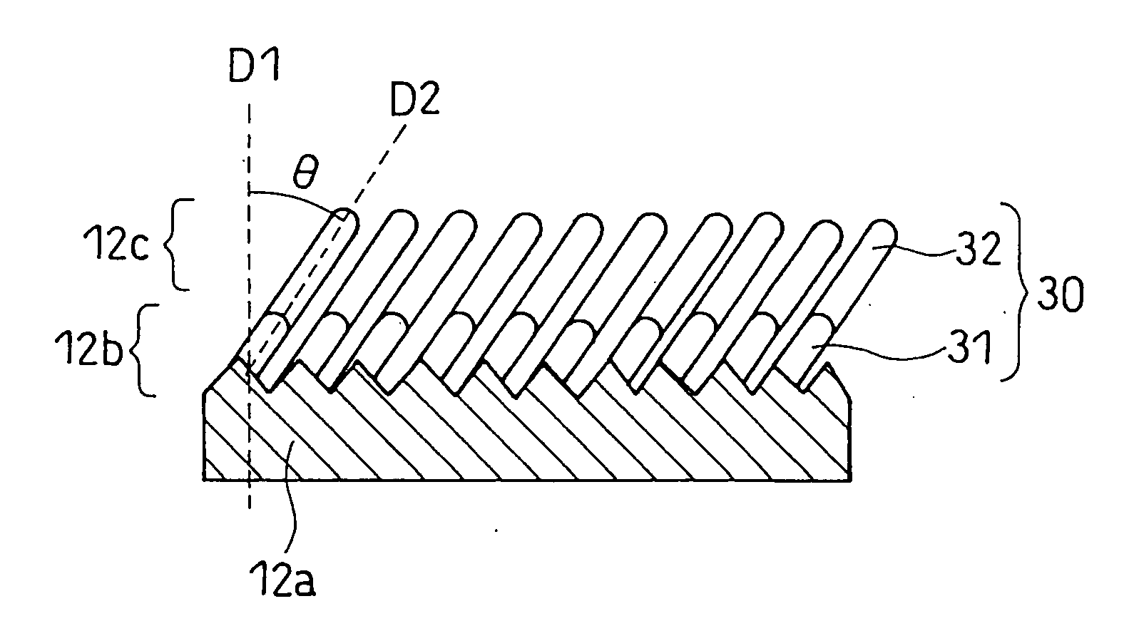
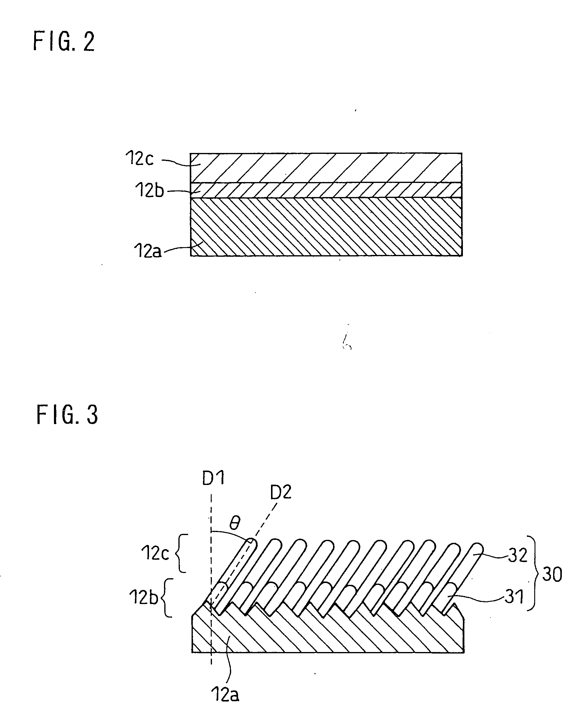
[0129] The counter electrode made of the lithium metal foil was opposed to the negative electrode active material layer 12c of the negative electrode 12, with a separator 13 interposed therebetween, to form a thin electrode assembly. The separator used was a 20-μm-thick polyethylene micro-porous film available from Asahi Kasei Corporation. This electrode assembly was inserted, to...

example 3

[0142] When the intermediate layer including silicon and oxygen is represented by SiOx, the range of x was examined.

[0143] The following negative electrodes 3A to 3E were produced in the same manner as in Example 1, except that in forming an intermediate layer, the oxygen flow rate and the deposition time were changed. Also, test batteries 3A to 3E were produced in the same manner as in Example 1 except for the use of the negative electrodes 3A to 3E. When the intermediate layer of each of these negative electrodes was formed, the temperature of the current collector was 320° C. Lithium was deposited on the active material layer in the same manner as in Example 1.

[0144] Negative Electrode 3A

[0145] A negative electrode 3A was produced in the same manner as in Example 1, except that in forming an intermediate layer, deposition was performed by setting the oxygen flow rate to 5 sccm and setting the deposition time to 20 seconds. A test battery 3A was produced in the same manner as i...


PUM

PropertyMeasurementUnit
thicknessaaaaaaaaaa
thicknessaaaaaaaaaa
thicknessaaaaaaaaaa

Abstract

A negative electrode for a lithium ion secondary battery includes a current collector, an intermediate layer formed on a surface of the current collector, and an active material layer formed on the intermediate layer. The current collector includes a metal capable of being alloyed with silicon. The active material layer includes an active material including silicon. The intermediate layer includes silicon and oxygen. The intermediate layer prevents the metal capable of being alloyed with silicon from diffusing into the active material layer. The diffusion of the constituent element of the current collector into the active material layer is suppressed.

Description

FIELD OF THE INVENTION [0001] The present invention relates to lithium ion secondary batteries, and, more particularly, to a negative electrode for lithium ion secondary batteries. BACKGROUND OF THE INVENTION [0002] With the recent development of portable devices such as personal computers and cellular phones, there is an increasing demand for batteries used as the power source for such devices. In such applications, batteries are required to operate at room temperature and provide high energy density and excellent cycle characteristics. To meet such requirements, silicon (Si) or tin (Sn), and oxides or alloys thereof are viewed as promising negative electrode active materials that can offer significantly high capacities. [0003] However, when such a material absorbs lithium, its crystal structure changes, so that its volume increases. A large volume change in an active material on charge / discharge results in, for example, a poor contact between the active material and a current coll...

Claims


Application Information

Patent Timeline
Patent Type & Authority Applications(United States)
IPC IPC(8): H01M4/36C23C16/00H01M4/04H01M4/134H01M4/1395H01M10/0525H01M10/36
CPCC23C14/226H01M4/134H01M4/1395H01M4/66Y02T10/7011H01M4/667H01M10/0525H01M2004/027Y02E60/122H01M4/664Y02E60/10Y02P70/50C23C14/10C23C14/14C23C14/225H01M4/0423H01M4/131H01M4/1391H01M4/628H01M10/052Y02T10/70
Inventor KOGETSU, YASUTAKAUGAJI, MASAYA
Owner PANASONIC CORP
Why Eureka
Try Eureka