

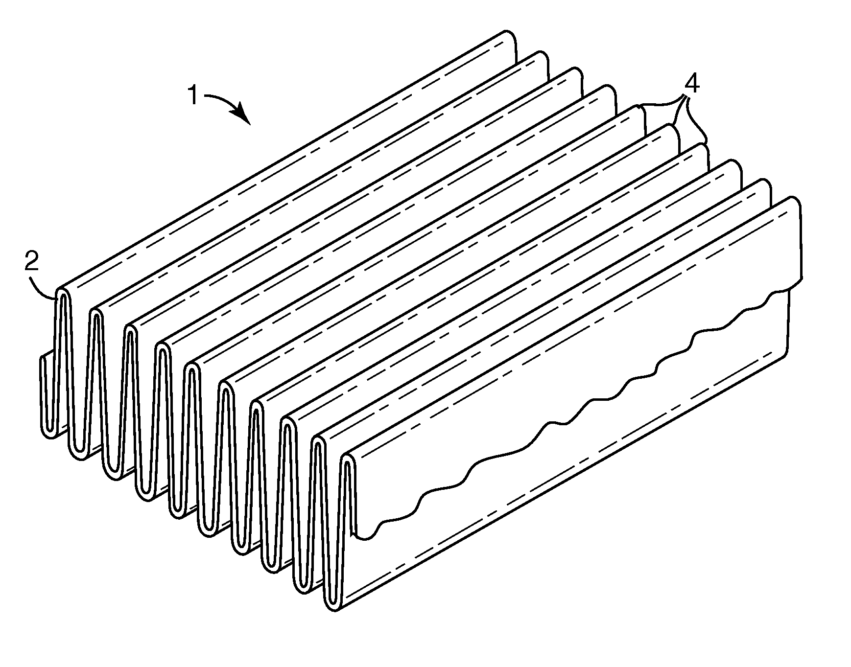
Pleated filter with bimodal monolayer monocomponent media
a monocomponent media and filter technology, applied in the direction of filtration separation, separation process, weaving, etc., can solve the problems of insufficient stiffness and strong to provide by itself a single-layer filter media having high efficiency and adequate strength, introducing additional cost and complexity to the filter product, and reducing product complexity and waste. , the effect of widening the filtration capability
- Summary
- Abstract
- Description
- Claims
- Application Information
AI Technical Summary
Benefits of technology
Problems solved by technology
Method used
Image


Examples
example 1
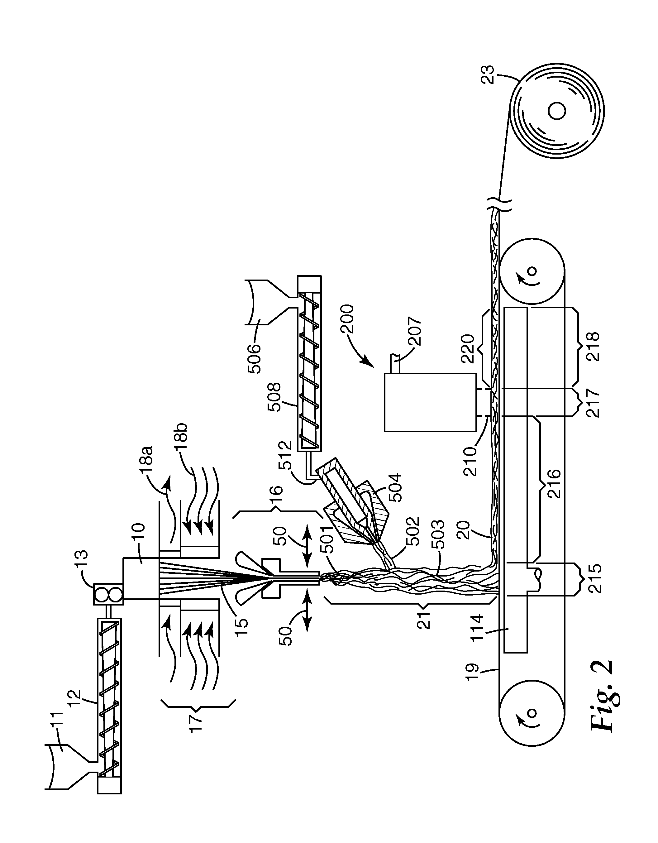
[0084]Nine webs were prepared using an apparatus as shown in FIG. 2 through FIG. 5 from polypropylene meltspun fibers and polypropylene meltblown microfibers. The meltspun fibers were prepared from FINA™ 3860 polypropylene having a melt flow index of 70 from Total Petrochemicals, to which was added 0.75 wt. % of CHIMASSORB 944 hindered-amine light stabilizer from Ciba Specialty Chemicals. The extrusion head 10 had 16 rows of orifices, with 32 orifices in a row, making a total of 512 orifices. The orifices were arranged in a square pattern (meaning that orifices were in alignment transversely as well as longitudinally, and equally spaced both transversely and longitudinally) with 0.25 inch (6.4 mm) spacing. The polymer was fed to the extrusion head at 0.8 g / hole / minute, where the polymer was heated to a temperature of 235° C. (455° F.). Two quenching air streams (18b in FIG. 2; stream 18a was not employed) were supplied as an upper stream from quench boxes 16 in. (406 mm) in height a...
example 2
[0095]The charged web of Run No. 1-8 was evaluated to determine additional flat web properties as shown below in Table 2A:
TABLE 2ABasis weight, gsm93Solidity, %11.7Thickness, mm0.89EFD, μm16Gurley Stiffness, mg622Pressure Drop at 13.8 cm / sec face velocity, mm H2O2.08DOP Penetration at 13.8 cm / sec face velocity, %24.14Quality Factor, QF, mm−1 H2O (DOP)0.68
[0096]The web was formed into a pleated filter element with a pleat height of 20 mm and a pleat spacing of 4.6 mm. The pleats were stabilized by gluing an expanded wire screen to the pleat tips on both sides of the filter. The filter was framed with a one-piece chipboard frame having 0.5 in. (12.7 mm) flaps folded over the filter perimeter on both sides of the filter element. The open area of the filter was approximately 7.4×12.0 in. (188×305 mm). The filter element was tested for initial pressure drop and initial fractional efficiency at a 300 ft / min (1.52 m / sec) face velocity. The initial pressure drop was 0.252 in. (6.4 mm) H2O. ...
example 3
[0100]Using a single extruder, a meltblowing die tip having a plurality of larger and smaller orifices like that shown in FIG. 8 and procedures like those described in Wente, Van A. “superfine Thermoplastic Fiber”, Industrial and Engineering Chemistry, vol. 48. No. 8, 1956, pp 1342-1346 and Naval Research Laboratory Report 111437, Apr. 15, 1954, a monocomponent monolayer meltblown web was formed from TOTAL™ EOD-12 polypropylene, a 1200 melt flow rate polymer available from Total Petrochemicals to which had been added 1% tristearyl melamine as an electret charging additive. The polymer was fed to Model 20 DAVIS STANDARD™ 2 in. (50.8 mm) single screw extruder from the Davis Standard Division of Crompton & Knowles Corp. The extruder had a 60 in. (152 cm) overall length, and a 30 / 1 length / diameter ratio. A Zenith 10 cc / rev melt pump metered the flow of polymer to a 10 in. (25.4 cm) wide drilled orifice meltblowing die whose original 0.012 in. (0.3 mm) orifices had been modified by drill...
PUM
| Property | Measurement | Unit |
|---|---|---|
| Fraction | aaaaa | aaaaa |
| Fraction | aaaaa | aaaaa |
| Fraction | aaaaa | aaaaa |
Abstract
Description
Claims
Application Information